
Peak power control technique for primary side controller operation in continuous conduction mode

Active Publication Date: 2017-04-11
FLEXTRONICS AP LLC
View PDF229 Cites 42 Cited by
  • Summary
  • Abstract
  • Description
  • Claims
  • Application Information

AI Technical Summary

Benefits of technology

The patent describes a power converter that can adjust its output voltage to regulate power consumption. The converter operates in two modes: a discontinuous conduction mode (DCM) for low power consumption and a continuous conduction mode (CCM) for high power consumption. The converter includes an isolation transformer, an output rectifier, and a control module. The control module determines the period of nominal power use and the period of high power use, and the converter operates accordingly. The technical effect of this design is to optimize the power converter's efficiency and regulate its output voltage during different power usage periods.

Problems solved by technology

Some circuits are subject to uncertain and undesirable functioning and even irreparable damage if supplied power falls outside a certain range.
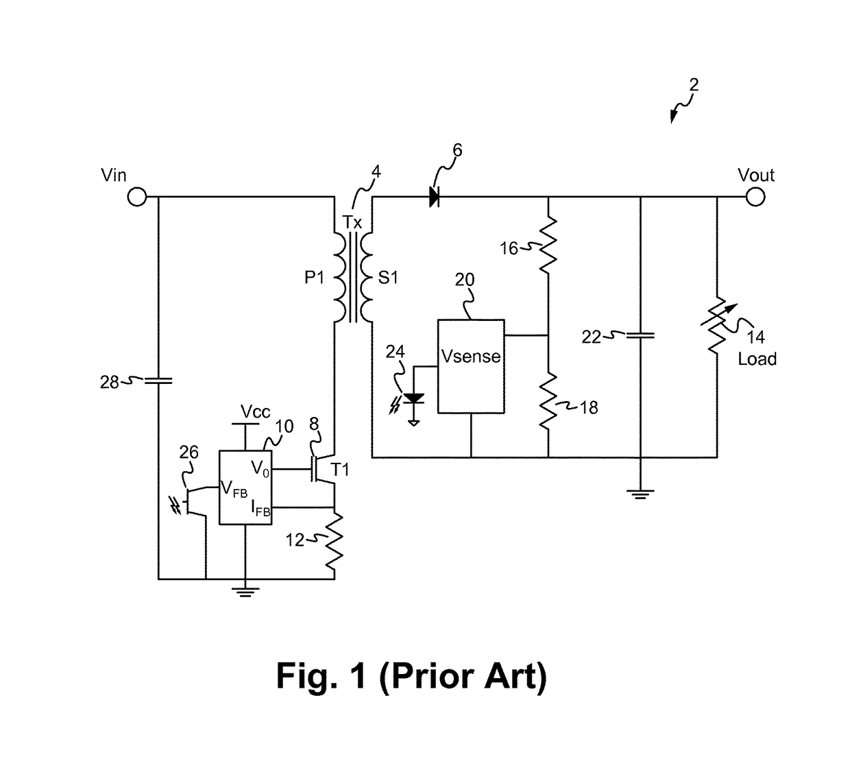
However, the use of an optical coupler circuit in and of itself presents issues.
Firstly, the optical coupler circuit adds extra cost.
In some applications, the optical coupler circuit can add more cost to the power converter than the isolation transformer.
The optical coupler circuit also adds to manufacturing and testing costs.
Furthermore, the performance of the optical coupler circuit degrades over time and therefore introduces another potential point of failure in the overall power converter.
The optical coupler circuit also has delays related to the operation of the optical diode and the optical transistor, and the operation of the optical diode requires a well defined DC level.
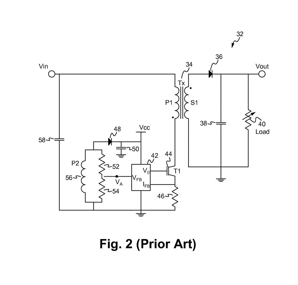
Although using such a power converter in the DCM is effective for low to mid range power applications, using the power converter in DCM is not practical for higher power applications, such as those applications approaching or exceeding 20 watts, because such an architecture is not electrically efficient, is larger in size and is not cost effective.
As such, using the power converter in the DCM for those applications having a relatively high average power, and also those applications having a relatively low or mid average power but durations of higher peak power, is not practical.
Operating the power converter of FIG. 2 in the CCM is also ineffective.
Since there is non-zero secondary side current while operating in CCM, there are always voltage losses associated with the transforming winding resistance and the secondary side diode voltage drop.
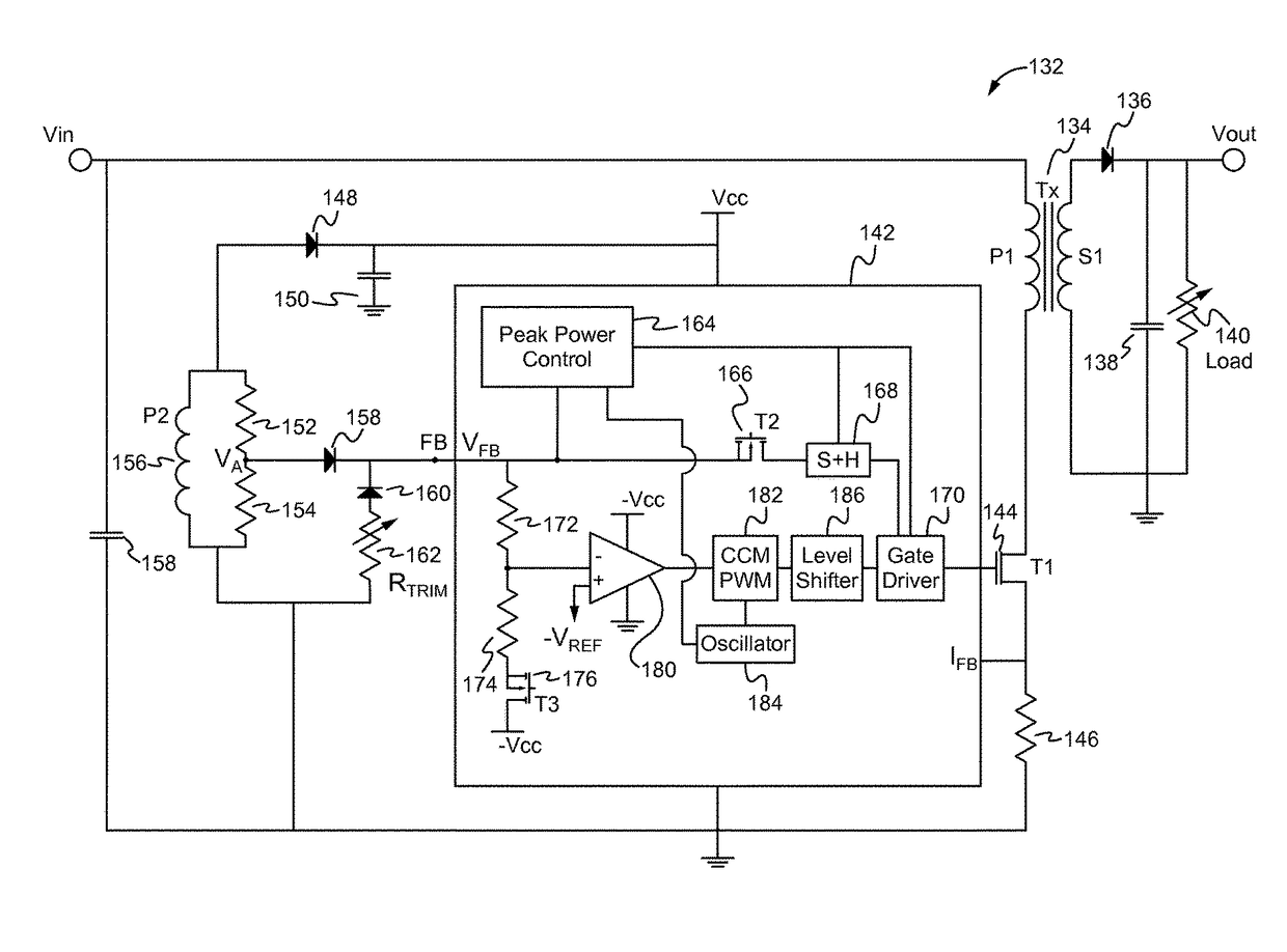
If the auxiliary winding voltage Vaux is used as a feedback signal as described above, it is difficult to compensate for these voltage losses and keep the output voltage in regulation when the primary side controller is operating in CCM during peak power demand.

Method used


Image

  • Peak power control technique for primary side controller operation in continuous conduction mode
  • Peak power control technique for primary side controller operation in continuous conduction mode
  • Peak power control technique for primary side controller operation in continuous conduction mode

Examples


Embodiment Construction

[0027]Embodiments of the present application are directed to a power converter. Those of ordinary skill in the art will realize that the following detailed description of the power converter is illustrative only and is not intended to be in any way limiting. Other embodiments of the power converter will readily suggest themselves to such skilled persons having the benefit of this disclosure.

[0028]Reference will now be made in detail to implementations of the power converter as illustrated in the accompanying drawings. The same reference indicators will be used throughout the drawings and the following detailed description to refer to the same or like parts. In the interest of clarity, not all of the routine features of the implementations described herein are shown and described. It will, of course, be appreciated that in the development of any such actual implementation, numerous implementation-specific decisions must be made in order to achieve the developer's specific goals, such...


PUM


Abstract

A power converter includes a primary side controller configured to operate the power converter in the discontinuous conduction mode during low to mid-power requirements and to operate the power converter in the continuous conduction mode during high or peak power requirements. The power converter includes a primary side auxiliary winding that provides a feedback signal to the primary side controller, and an adjusted resistor and diode circuit which is coupled to a multi-function feedback (FB) pin of the primary side controller. The primary side controller monitors for a peak power demand, upon detection of which a negative supply rail is enabled, which is used to compensate for voltage losses due to non-zero current while operating in the CCM, thereby enabling output voltage regulation while operating in the CCM during peak power demand.

Description

FIELD OF THE INVENTION[0001]The present invention relates to the field of power converters. More particularly, the present invention relates to the control of power converters.BACKGROUND[0002]In many applications a power converter is required to provide a voltage within a predetermined range formed from a voltage source having a different voltage level. Some circuits are subject to uncertain and undesirable functioning and even irreparable damage if supplied power falls outside a certain range. More specifically, in some applications, a precise amount of power is required at known times. This is referred to as regulated power supply. In order to control a power converter to deliver a precise amount of power as conditions require, some form of control of the power converter is required. This control can occur on the primary side of an isolation transformer or the secondary side. A closed loop feedback control system is a system that monitors some element in the circuit, such as the c...

Claims


Application Information

Patent Timeline
IPC IPC(8): H02M3/335H02M1/00
CPCH02M3/33507H02M2001/0025H02M3/33523Y02B70/10H02M1/0025H02M1/0032
Inventor TELEFUS, MARK
Owner FLEXTRONICS AP LLC
Learn More