
Portable vaporizer and method for temperature control

a vaporizer and portability technology, applied in the field of vaporizers, can solve the problems of charring of botanical materials, requiring several minutes of heat-up time for vaporizers, and affecting the use of tobacco products,

Inactive Publication Date: 2015-05-14
NWT HLDG
View PDF2 Cites 136 Cited by
  • Summary
  • Abstract
  • Description
  • Claims
  • Application Information

AI Technical Summary

Benefits of technology

The present invention is a vaporizer that is designed to control the power provided to vaporize a botanical material based on the temperature of the vaporizer. This is accomplished by measuring the temperature of the vaporizer and decreasing the electric power to the heater if the temperature increases. The invention also includes a method of controlling the electric power by measuring the voltage of the battery providing power to the heater and adjusting the duty cycle of the battery voltage accordingly. The vaporizer provides a consistent and safe experience for users who enjoy the benefits of vaporized botanical materials.

Problems solved by technology

For many botanical materials it is the volatiles, such as the nicotine present in tobacco, that provide a physiological response in the consumer, while the combustion products may actually be harmful.
This may result in high temperatures, leading to singing and charring of the botanical material near the heat source.
Further, many prior art vaporizers require several minutes of heat-up time as they need to heat both the mass of the botanical material and a holder of the material to a desired temperature before they can extract volatile vapors.
Further, since the heating is typically continuous, rather than on-demand, many existing vaporizers use their power inefficiently as they are often providing heat to maintain a steady state of elevated temperature that does not correspond to the user's intended duty-cycle of intermittent inhalation of the vapors produced.

Method used


Image

  • Portable vaporizer and method for temperature control
  • Portable vaporizer and method for temperature control
  • Portable vaporizer and method for temperature control

Examples


Embodiment Construction

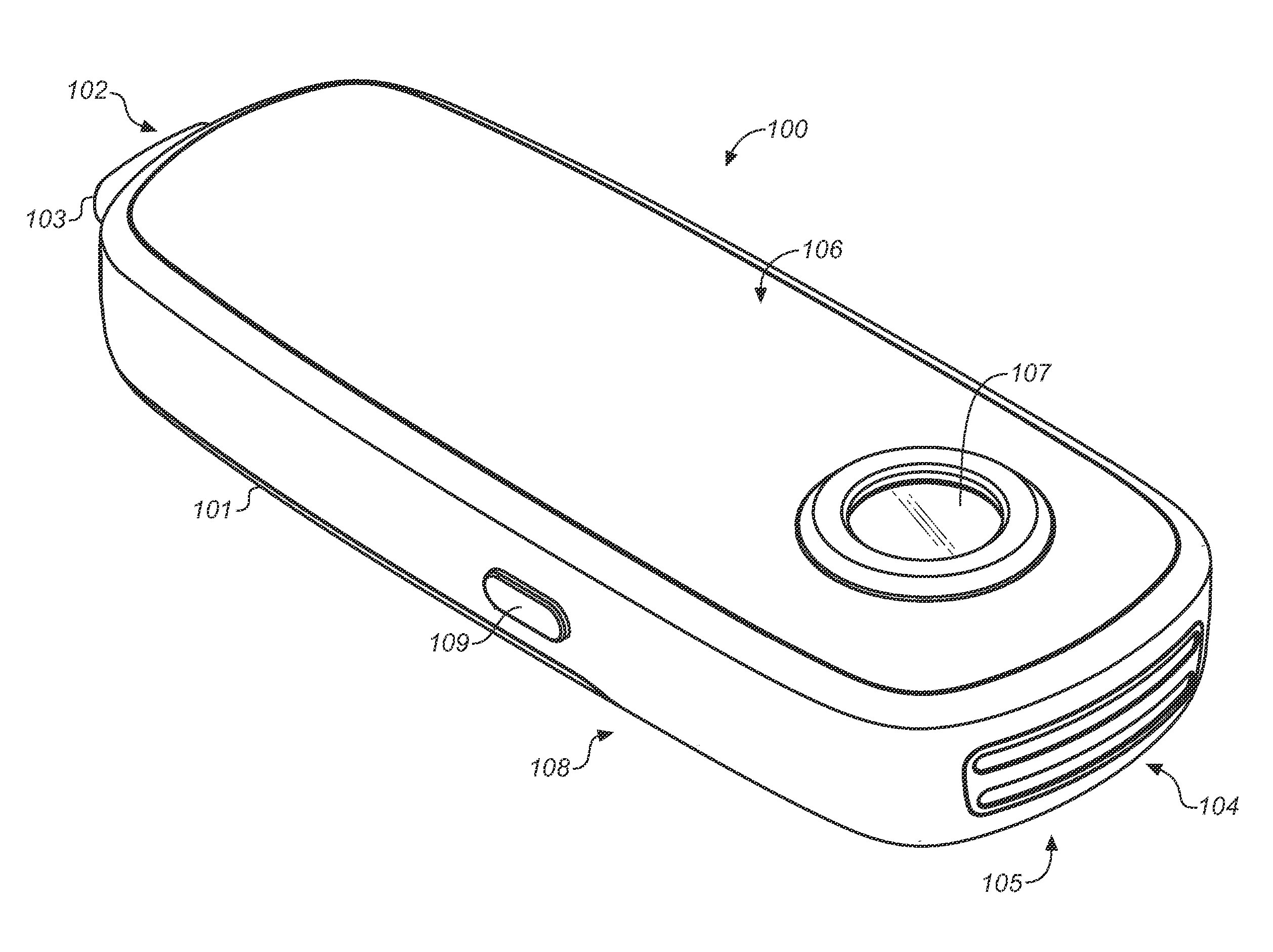
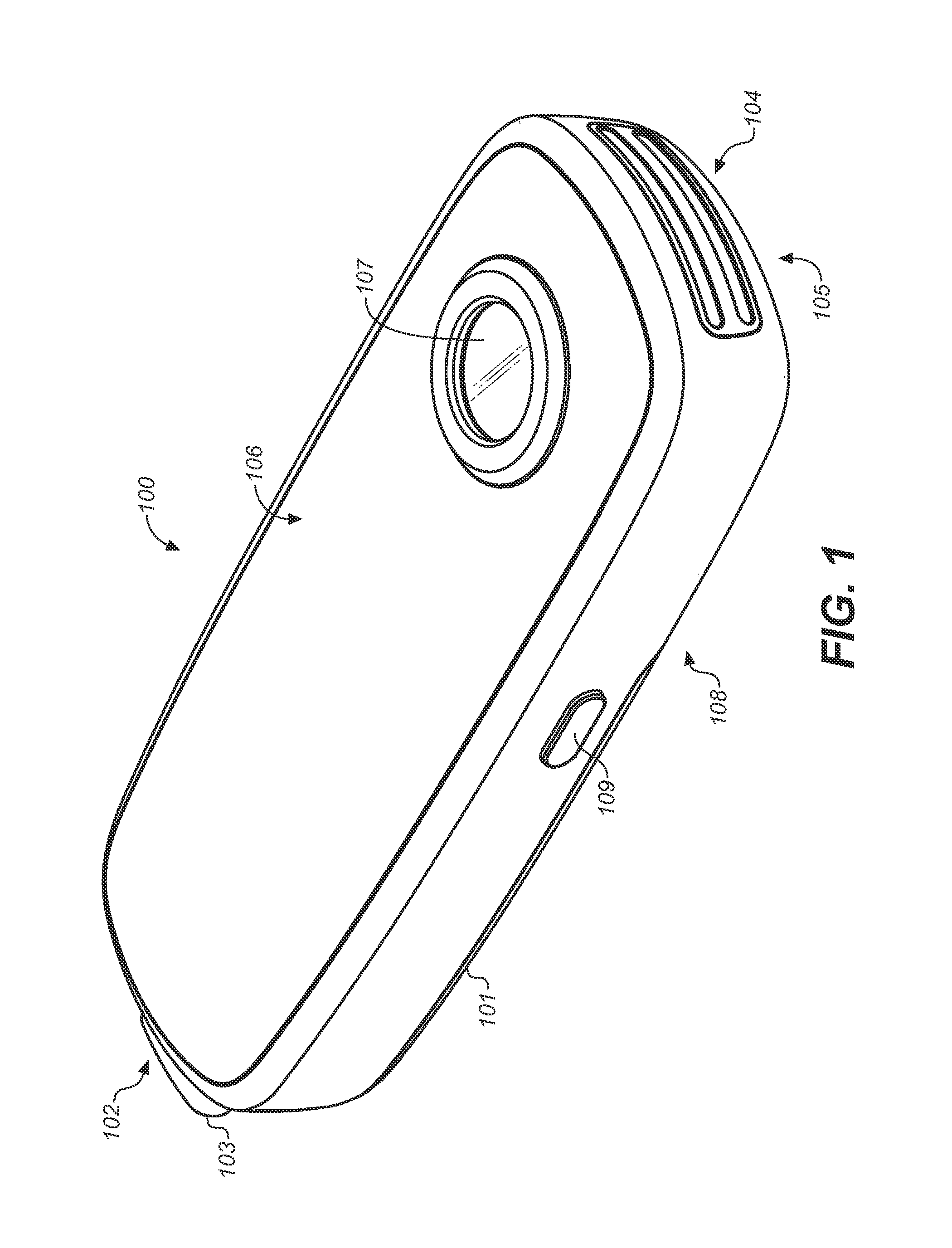
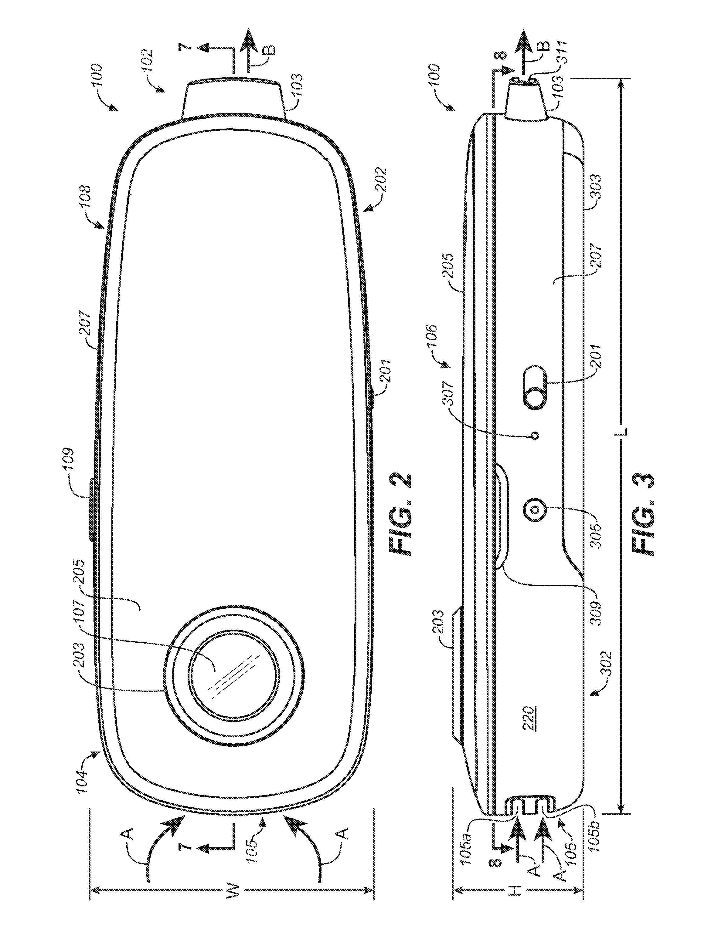
[0029]FIG. 1 is a top perspective view of one embodiment of a hand-held vaporizer 100, and FIGS. 2, 3, 4, and 5 are, respectively, views of a top side 106, a left side 202, a distal end 104, and a proximal end 102 of the vaporizer.

[0030]Vaporizer 100 includes a housing 101 having a mouthpiece 103 with an opening 311 into the vaporizer at proximal end 102, an air inlet 105 at distal end 104, and a window 107 on top side 106 through which one can view a botanical material placed within the vaporizer, and a push-button switch 109 on a right side 108. Left side 202 includes a power switch 201, a power connector 305, indicator lights 307, and a recess 309.

[0031]Housing 101 is formed from a rigid material, and may include one or more pieces or layers of metal or plastic. Thus, for example, sides 108, 202, and ends 102, 104 include a case 207 and a removable bottom panel 303, and top side 106 includes an elongated portion 205 and a bezel 203 protruding above and surrounding window 107.

[003...


PUM


Abstract

A vaporizer and method of vaporizing a botanical material is described. Embodiments of the apparatus include a self-contained, fully enclosed, battery operated vaporizer having an air inlet and a mouthpiece. The vaporizer includes a window for viewing a botanical material contained therein and a heating element that is also visible through the window and through an air inlet. The vaporizer also includes a push-button switch that rapidly provides power to heat air, which is then drawn through the botanical material by inhaling. Embodiments of the method include utilizing a push-button switch for heating vaporizer air and viewing the glow of the heating element as a signal that the vaporizer is ready for use. In certain embodiments, electric power for heating the air is varied according to the temperature of the vaporizer. Certain other embodiments measure the battery voltage and adjust a heater duty cycle according to the measured voltage.

Description

CROSS-REFERENCE TO RELATED APPLICATIONS[0001]This application claims the benefit of U.S. Provisional Application No. 61 / 902,038, filed Nov. 8, 2013, the contents of which are hereby incorporated by reference in its entiretyBACKGROUND OF THE INVENTION[0002]1. Field of the Invention[0003]The present invention generally relates to the field of vaporizers for consuming botanical materials, and more particularly to an apparatus and method for operating a vaporizer for heating the materials.[0004]2. Discussion of the Background[0005]Devices for consuming botanical materials, including but not limited to tobacco, flowers, botanical blend, or aromatic herbs, commonly ignite the botanical materials, requiring that the consumer inhale products of combustion along with any volatile compounds that are present. For many botanical materials it is the volatiles, such as the nicotine present in tobacco, that provide a physiological response in the consumer, while the combustion products may actuall...

Claims


Application Information

Patent Timeline
IPC IPC(8): A24F47/00A24F40/20A24F40/50A24F40/60
CPCA24F47/008A24F40/60A24F40/50A24F40/20
Inventor ROBINSON, ALEXANDERWILLIAMS, MARK
Owner NWT HLDG
Learn More