Adjacent vehicle detection device
a detection device and parallel running technology, applied in measurement devices, using reradiation, instruments, etc., can solve the problems of rare chance that a road surface is detected, degradation of responsiveness, etc., to increase the number of times of determining, and suppress the erroneous detection
- Summary
- Abstract
- Description
- Claims
- Application Information
AI Technical Summary
Benefits of technology
Problems solved by technology
Method used
Image
Examples
embodiment 1
[0041](Embodiment 1)
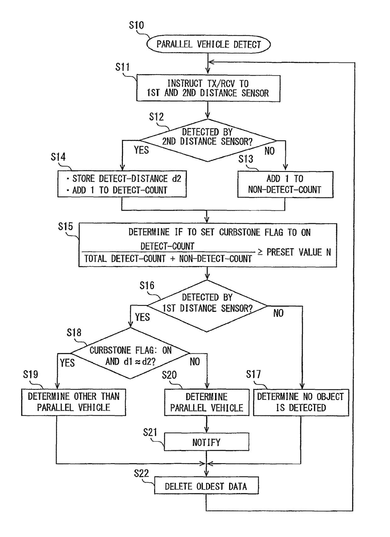
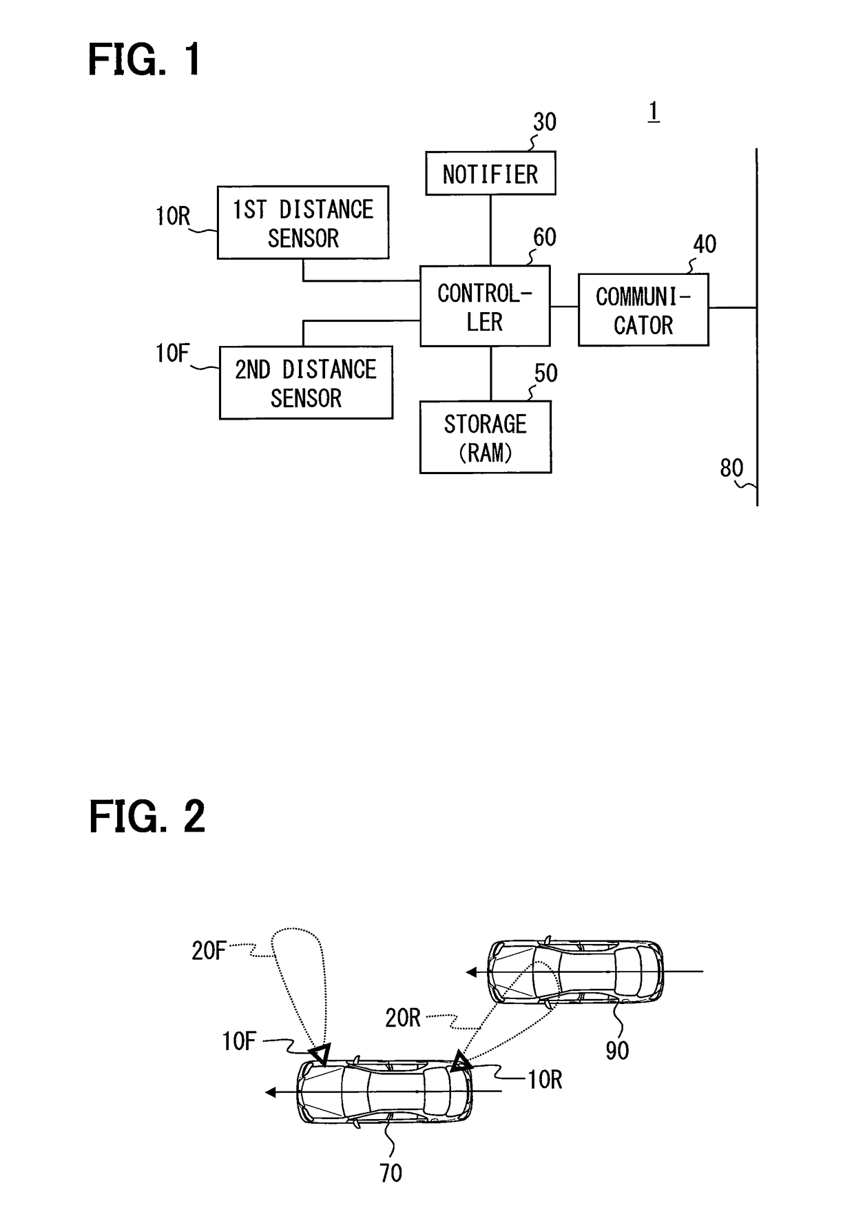
[0042]Hereinafter, embodiments of the present disclosure will be explained in detail with reference to the accompanying drawings. As illustrated in FIG. 1, a parallel running vehicle detecting apparatus 1 according to Embodiment 1 is provided with a first distance sensor 10R, a second distance sensor 10F, a notifier 30, a communication device 40, a storage 50, and a controller 60. The parallel running vehicle detecting apparatus 1 configured in this way is mounted on a vehicle 70 (refer to FIG. 2).
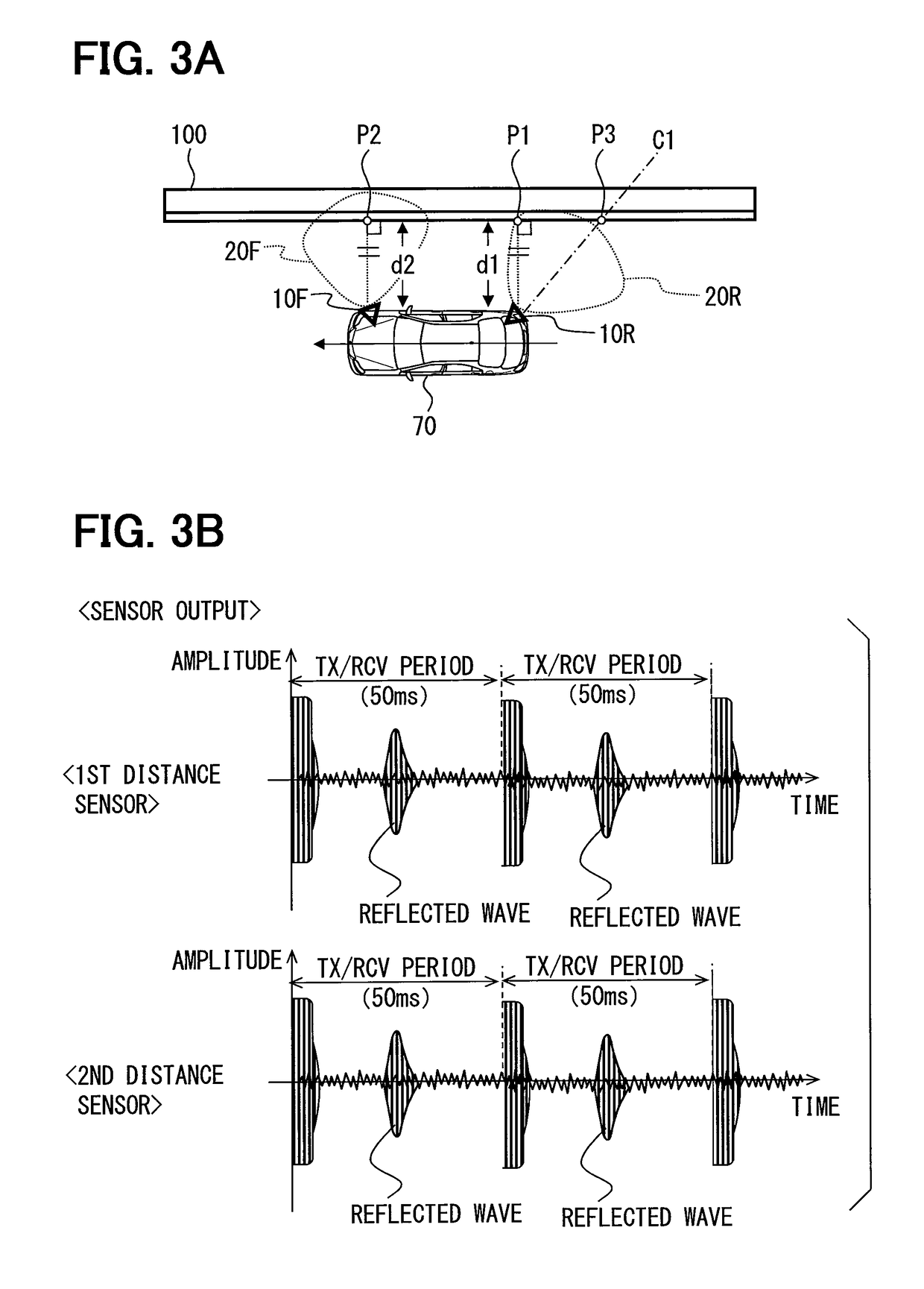
[0043]The pair of the first distance sensor 10R and the second distance sensor 10F is ultrasonic sensors, and they are arranged so as to have a detection area nearest to a vehicle and on a lateral side of either right or left of the vehicle. Here, the lateral side does not restrict the position in the anteroposterior direction to the range from a front end to a back end of the vehicle; however, it also includes a diagonal front (front lateral side) and a diagonal rear (...
embodiment 2
[0075](Embodiment 2)
[0076]Next, Embodiment 2 is explained. In the explanation of Embodiment 2 and subsequent embodiments, the same elements as explained already are referred to by the same references as used in previous embodiments, unless otherwise referred to in particular.
[0077]In Embodiment 1, the first parallel running vehicle determination condition takes into consideration whether the first detection distance d1 is in the metric division that is considered to be the distance to a curbstone, etc., whereas the second parallel running vehicle determination condition does not take this into consideration.
[0078]In Embodiment 2, in addition to the first parallel running vehicle determination condition and the second parallel running vehicle determination condition, another condition is provided which determines whether, within a predetermined time or a predetermined mileage, the number of times the object is detected in the same metric division has exceeded a predetermined value.
[0...
embodiment 3
[0081](Embodiment 3)
[0082]Next, Embodiment 3 is explained. The mechanical configuration of Embodiment 3 is the same as that of Embodiment 1, and it has the configuration illustrated in FIG. 1. The difference from Embodiment 1 includes control performed by the controller 60. In Embodiment 3, in lieu of the processing illustrated in FIG. 4, the parallel running vehicle detection S30 illustrated in FIG. 5 is performed.
[0083]First, at Step S31, an instruction for transmission and reception is issued to the first distance sensor 10R and the second distance sensor 10F. At Step S32, it is determined whether the second distance sensor 10F has detected an object.
[0084]When the second distance sensor 10F has detected an object (YES at S32), at Step S33, a stationary object flag is set to ON, and a flag setup time (corresponding to the suspending period) is determined.
[0085]The flag setup time is calculated by dividing a flag setting interval by the current vehicle velocity. In the above, the ...
PUM
 Abstract
Description
Claims
Application Information
 - R&D
- Intellectual Property
- Life Sciences
- Materials
- Tech Scout
- Unparalleled Data Quality
- Higher Quality Content
- 60% Fewer Hallucinations
Browse by: Latest US Patents, China's latest patents, Technical Efficacy Thesaurus, Application Domain, Technology Topic, Popular Technical Reports.
© 2025 PatSnap. All rights reserved.Legal|Privacy policy|Modern Slavery Act Transparency Statement|Sitemap|About US| Contact US: help@patsnap.com


