Fan control circuit

a technology of control circuit and fan, applied in the direction of machines/engines, electronic commutators, instruments, etc., can solve the problem of unsatisfactory fan operation, and achieve the effect of increasing the precision of fan control and effective solving the problem

Active Publication Date: 2017-03-14
ALPHA NETWORKS INC
View PDF3 Cites 0 Cited by
  • Summary
  • Abstract
  • Description
  • Claims
  • Application Information

AI Technical Summary

Benefits of technology

[0007]In view of the fact that a conventional control circuit configured for converting a PWM voltage signal fails to meet the lowest driving voltage value of a fan and cannot turn off the fan, the inventor of the present invention incorporated years of practical experience into extensive research and tests and finally succeeded in developing a fan control circuit as disclosed herein. The fan control circuit is intended to effectively solve the various problems of the conventional circuits and increase the precision in fan control.
[0009]Another objective of the present invention is to provide the foregoing fan control circuit, wherein the current expansion circuit is composed of two transistors connected in a cascade, and wherein the output driving voltage signal is delivered to the amplifier circuit through negative feedback. Therefore, the circuit design of present invention not only features fast response, but also enhances the stability of the fan control circuit lest the precision of signal processing be compromised by the influence of temperature.

Problems solved by technology

As previously mentioned, the failure makes it impossible for a fan to work in the ideal fashion even after conversion of the PWM voltage signal.

Method used


Image

  • Fan control circuit
  • Fan control circuit
  • Fan control circuit

Examples


Embodiment Construction

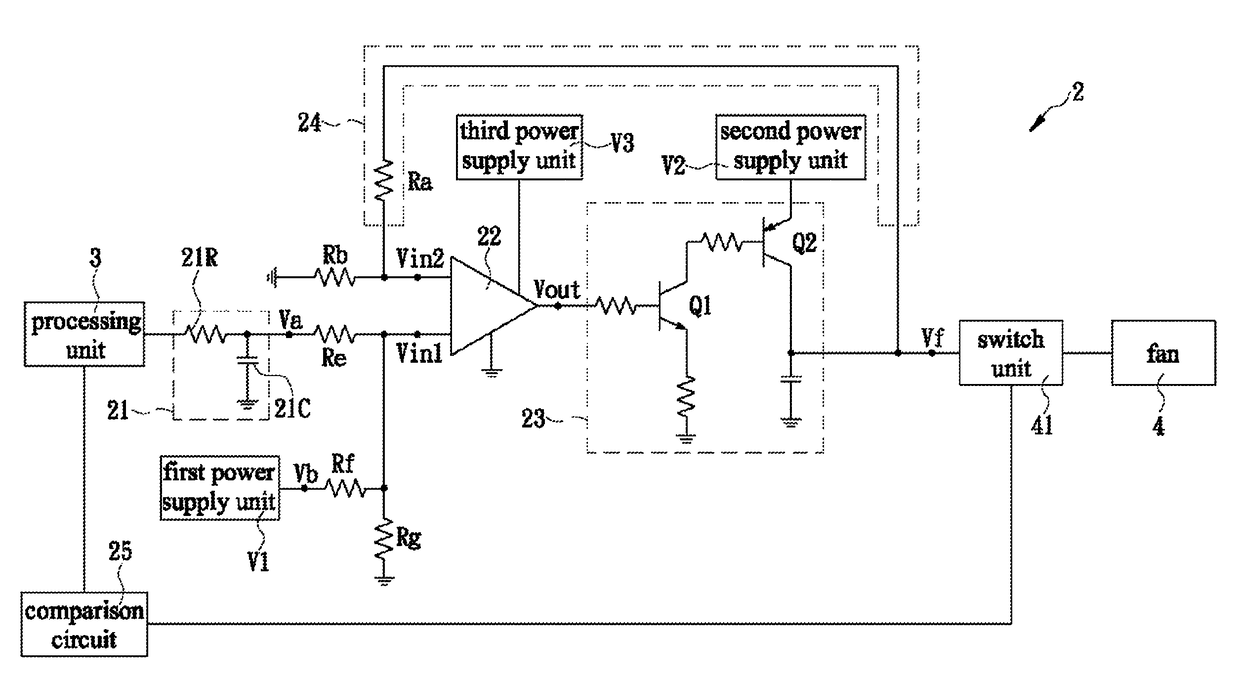
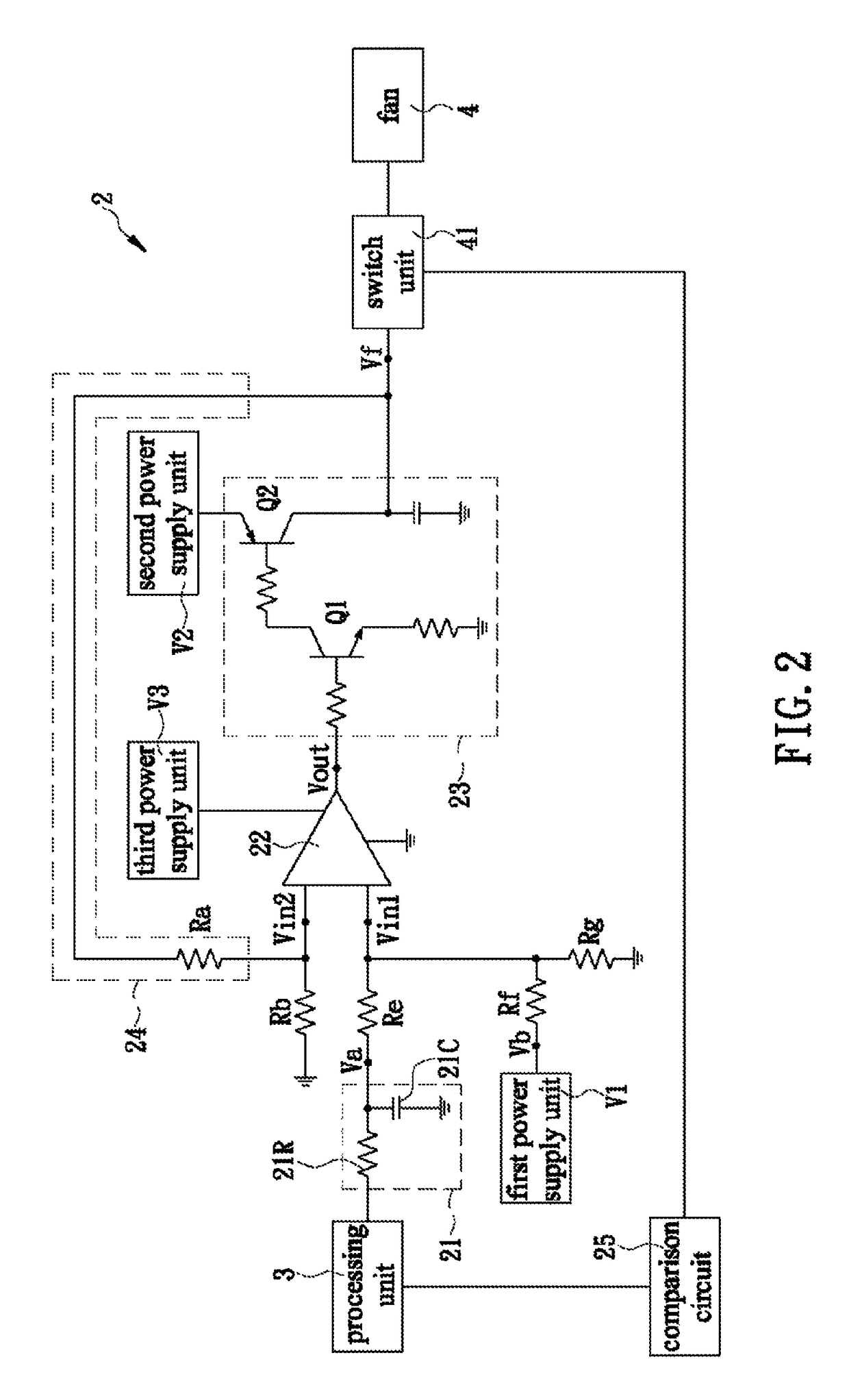
[0014]The present invention discloses a fan control circuit. Referring to FIG. 2 for the first preferred embodiment of the present invention, the fan control circuit 2 is applied to the circuit board of an electronic device (e.g., a computer) and includes a processing unit 3 and a fan 4. The processing unit 3 and the fan 4 are electrically connected through the fan control circuit 2 on the circuit board. The fan control circuit 2 includes a filter circuit 21, an amplifier circuit 22, a current expansion circuit 23, and a feedback circuit 24. The filter circuit 21 is composed of a first resistor 21R and a first capacitor 21C. The input end of the filter circuit 21 is electrically connected to the processing unit 3 in order to receive a PWM voltage signal from the processing unit 3. The PWM voltage signal is converted into a DC voltage signal via the first resistor 21R and the first capacitor 21C, and the DC voltage signal is in direct proportion to the duty cycle of the PWM voltage s...


PUM

PropertyMeasurementUnit
voltageaaaaaaaaaa
voltageaaaaaaaaaa
voltageaaaaaaaaaa

Abstract

The present invention is to provide a fan control circuit, which includes a filter circuit for converting a pulse-width modulation (PWM) voltage signal into a DC voltage signal; an amplifier circuit having an input end for receiving the DC voltage signal and a static voltage signal and generating an amplified voltage signal at an output end thereof; a current expansion circuit configured to perform current expansion on the amplified voltage signal and thereby generate a driving voltage signal for a fan; and a feedback circuit connected between another input end of the amplifier circuit and an output end of the current expansion circuit so that magnitude of the driving voltage signal is in direct proportion to the duty cycle of the PWM voltage signal and is greater than or equal to a lowest driving voltage value of the fan when the duty cycle of the PWM voltage signal approaches zero.

Description

FIELD OF THE INVENTION[0001]The present invention relates to a control circuit, more particular to a fan control circuit, which is able to convert a pulse-width modulation (PWM) voltage signal into a DC voltage signal, generate an amplified voltage signal according to the DC voltage signal and a static voltage signal, perform current expansion on the amplified voltage signal to generate a driving voltage signal for a fan, and control magnitude of the driving voltage signal to be in direct proportion to the duty cycle of the PWM voltage signal and be greater than or equal to a lowest driving voltage value of the fan when the duty cycle of the PWM voltage signal approaches zero.BACKGROUND OF THE INVENTION[0002]With the rapid development of microelectronics, the technology of central processing units (CPUs) gradually matures. While the processing efficiency and speed of CPUs are improving, the increase of their operating clocks leads to the generation of more heat during operation; the...

Claims


Application Information

Patent Timeline
Patent Type & Authority Patents(United States)
IPC IPC(8): H02P6/18H02P7/29F04D27/00G01N21/00G08B3/00F04D25/06
CPCF04D27/004H02P7/29F04D25/0613Y02B30/70
Inventor LV, CHENG-XIAN
Owner ALPHA NETWORKS INC
Why Eureka
Try Eureka