Liquid-consuming apparatus

a technology of liquid-consuming apparatus and cover, which is applied in the direction of printing, other printing apparatus, etc., can solve the problems of reducing the rigidity of the cover and the inability to rotate smoothly, and achieve the effect of reducing the twisting of the cover

Active Publication Date: 2017-03-07
BROTHER KOGYO KK
View PDF12 Cites 0 Cited by
  • Summary
  • Abstract
  • Description
  • Claims
  • Application Information

AI Technical Summary

Benefits of technology

[0007]The above recording apparatus, however, is required that the cover has an opening in order to form the transparent portion. This reduces the rigidity of the cover. As a result, there is fear that the cover might be twisted by the force to rotate the cover so that the cover might not rotate smoothly.
[0008]The present teaching has been made in view of the abovementioned circumstances, and an object of the present teaching is to provide a liquid-consuming apparatus in which a cover having an opening is smoothly rotatable.
[0010]According to the liquid-consuming apparatus having the above structure, it is possible to reduce the twisting of the cover caused by the force applied to the tab by a user. Thus, the cover can rotate smoothly between the covering position and the exposure position.

Problems solved by technology

This reduces the rigidity of the cover.
As a result, there is fear that the cover might be twisted by the force to rotate the cover so that the cover might not rotate smoothly.

Method used


Image

  • Liquid-consuming apparatus
  • Liquid-consuming apparatus
  • Liquid-consuming apparatus

Examples


modified embodiment 1

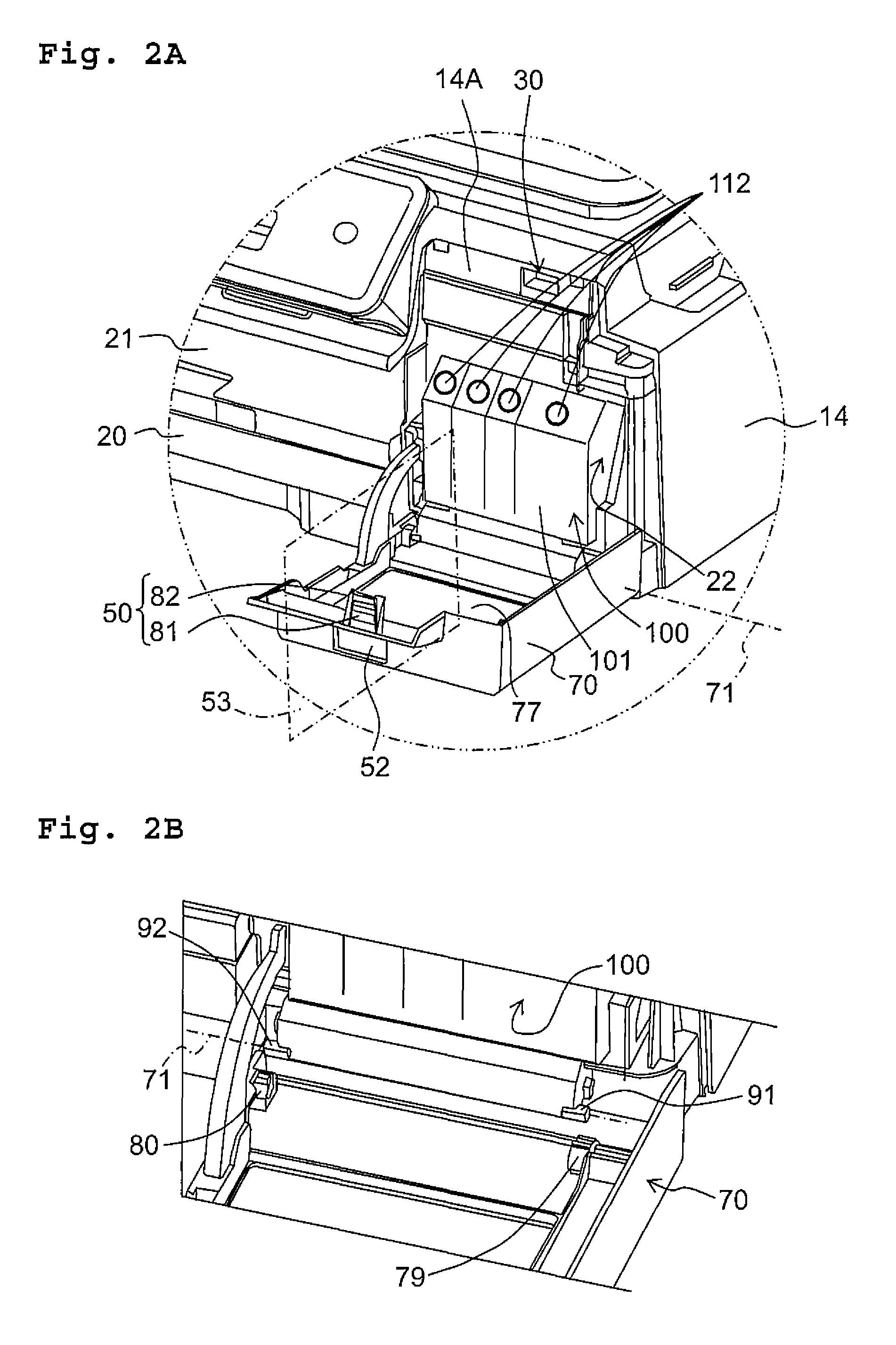
[0088]In the above embodiment, the recess 30 corresponds to the engaging target part. Further, in the above embodiment, the engaging part 50 protrudes from the inner surface of the protruding wall 86 in the same protruding direction as the side walls 73, 74, and 75. The engaging target part, however, is not limited to the recess 30 provided that the engaging target part is engageable with the engaging part to hold the cover 70 in the covering position. Further, the shape of the engaging part is not limited to the protruding shape provided that the engaging part is engageable with the engaging target part.

[0089]For example, unlike the above embodiment, the target engaging part may protrude frontward from the front surface of the casing 14, and the engaging part may be a recess formed in the inner surface of the protruding wall 86.

modified embodiment 2

[0090]In the above embodiment, the engaging part 50 is provided in the protruding wall 86. The engaging part 50, however, may be provided in any part other than the protruding wall 86, provided that the engaging part 50 engages with the recess 30. For example, the engaging part 50 may be provided in the side wall 73.

modified embodiment 3

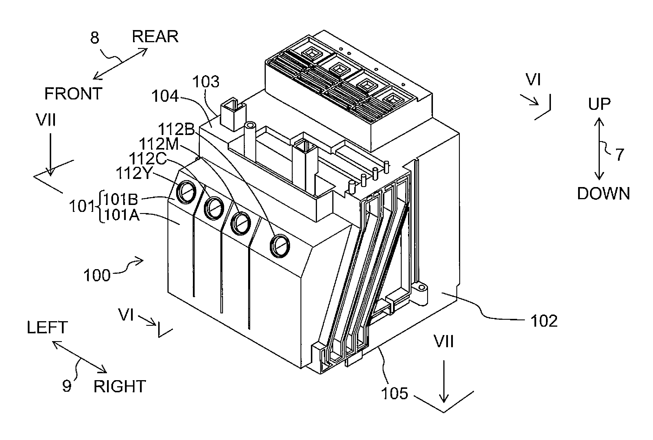
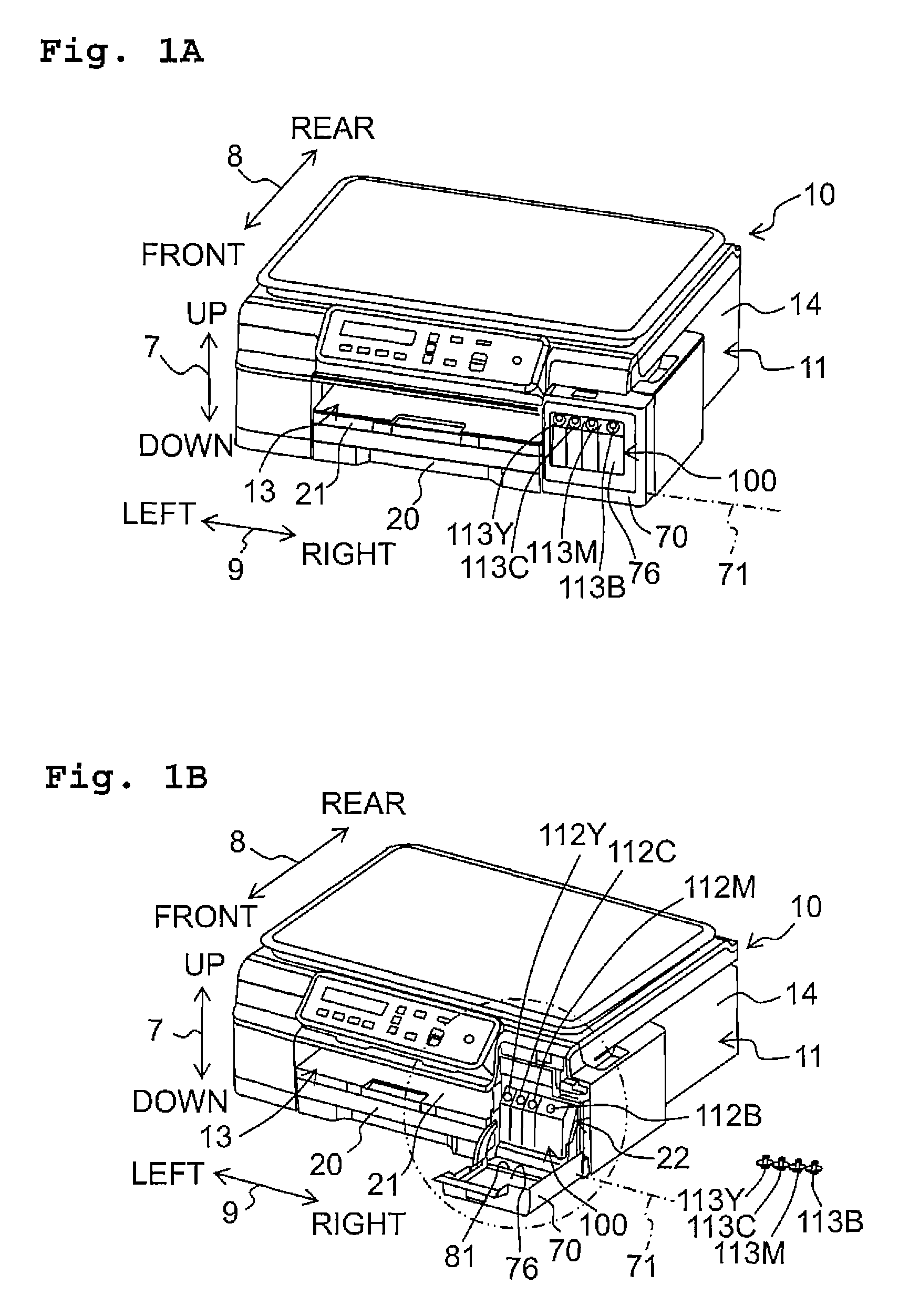
[0091]In the above embodiment, the left-right direction 9 corresponds to the further direction. That is, the cover 70 is rotatable, between the covering position where the front wall 101 is covered with the cover 70 and the exposure position where the front wall 101 is exposed, around the rotation axis 71 extending in the left-right direction 9. In other words, the cover 70 is configured to cover the opening 22 formed in the front surface of the casing 14 from the front side.

[0092]The further direction, however, is not limited to the left-right direction 9. For example, the front-rear direction 8 may be the further direction. In this case, the cover 70 is rotatable, between the covering position where the right wall 102 or the left wall 103 is covered with the cover 70 and the exposure position where the right wall 102 or the left wall 103 is exposed, around the rotation axis extending in the front-rear direction 8. In other words, the cover 70 is configured to cover the opening for...


PUM


Abstract

A liquid-consuming apparatus includes: a tank including a liquid chamber, an upstanding wall facing a particular direction, and an inlet formed in a surface of the tank; a liquid-consuming unit consuming liquid stored in the liquid chamber; a cover rotatable between a covering position where the upstanding wall is covered with the cover and an exposure position where the upstanding wall is exposed, around a rotation axis extending in a further direction; and a casing including an engaging target part which holds the cover in the covering position, and supporting the tank, liquid-consuming unit, and cover. The cover includes: an engaging part to engage with the engaging target part in the state that the cover is in the covering position; and a tab which is subjected to an operation for releasing an engagement between the engaging part and the engaging target part.

Description

CROSS REFERENCE TO RELATED APPLICATION[0001]The present application claims priority from Japanese Patent Application No. 2014-222268, filed on Oct. 31, 2014, the disclosure of which is incorporated herein by reference in its entirety.BACKGROUND[0002]Field of the Invention[0003]The present teaching relates to a liquid-consuming apparatus having a tank which can be replenished with liquid through an inlet.[0004]Description of the Related Art[0005]There is conventionally known a liquid-consuming apparatus including a tank and a liquid-consuming unit. The tank can be replenished with liquid through an inlet. The liquid-consuming unit consumes the liquid stored in the tank. Further, there is known a recording apparatus including a cover, which is rotatable between a covering position where an ink tank is covered with the cover and an exposure position where an inlet provided in the ink tank is exposed. This cover includes a transparent portion for allowing a user to visually confirm a re...

Claims


Application Information

Patent Timeline
Patent Type & Authority Patents(United States)
IPC IPC(8): B41J2/175B41J29/13
CPCB41J2/17553B41J2/1752B41J2/17509B41J2/17513B41J29/13B41J2/17523
Inventor OSAKABE, YOSHINORIHIGUCHI, TOMOHISA
Owner BROTHER KOGYO KK
Why Eureka
Try Eureka