Laminate pre-form for a wind turbine blade

a technology of laminated preform and wind turbine blade, which is applied in the manufacture of final products, machines/engines, other domestic articles, etc., can solve the problems of increasing the elasticity of laminate in an undesired fashion, and the collapse of evacuation channels, so as to reduce the occurrence of gas pockets

Active Publication Date: 2017-02-28
VESTAS WIND SYST AS
View PDF3 Cites 1 Cited by
  • Summary
  • Abstract
  • Description
  • Claims
  • Application Information

AI Technical Summary

Benefits of technology

[0011]The fibres extending in an oblique direction with respect to said length direction will form vacuum-paths across the laminate pre-form. Further, gas escape paths are provided through the material in a vertical direction via an open structure of the non-continuous layer(s) of resin. Where these paths are inhibited in a local area due to local variation in the material, the distribution channel can divert gas in the length direction of the laminate around the local inhibition. The evacuation of the air from the laminate take place through the laminate, which at the beginning of the curing process is a porous structure allowing air to be evacuated. During the curing process the porosity is gradually decreased such that in the end of the curing process the laminate forms a substantially dense structure with a low porosity, suitably down to below 0,5%. In the curing process, the gradual decrease of the porosity will lead to a reduced capacity of air removal through the laminate. In other words, the distribution channel is arranged to redistribute evacuation flow from an area of the laminate pre-form having lower air removal capacity to another area having higher air removal capacity. The local air removal capacity will largely depend on how far the curing process has proceeded in the area concerned. The inventive laminate pre-form thereby allows air trapped within the structure to be removed in a very efficient way.
[0012]Furthermore, by arranging the distribution channels in the length direction of the laminate and parallel to the fibre tows, the channels may be formed without bending or stretching the continuous fibres in the fibre tows. In the event the channels would be running in a cross direction to the extension of the fibre tows, the individual fibres would be curled by an imprinting of a channel into the laminate. After curing of the laminate by application of heat, the curled property of the continuous structure will remain. This will increase the elasticity of the laminate in an undesired fashion. On the other hand, in the event the distribution channels and the fibre tows extend in the length direction, imprinting of the channels will not bend or curl the continuous fibres in the fibre tows, which leads to that the desired rigidity of the laminate will be obtained.
[0017]Laminate structures made with these materials may be very long, for example up to 40-80 m, but having a narrow width, for example less than 1 m,—in these components, the biaxial fabric will form a vacuum-path across the part (i.e. across the narrow dimension) successfully enough. Vacuum paths in the vertical direction will be provided by the arrangement of the layer(s) of resin in a non-continuous fashion, that is by arranging the layers of resin with an open area. However, due to local variation in the material sometimes the path can be inhibited in a local area—in which case having an additional longitudinal vacuum path that can divert ‘around’ the local inhibition is attractive. This allows other areas of higher permeability to transmit their vacuum to the local inhibited area that would otherwise have a lower vacuum level.
[0018]Preferably, the prepreg or semi-preg envelope is a biaxial prepreg, e.g. a 600-1200 gsm+−45 deg biaxial E-glasssemipreg or prepreg. Alternatively the envelope may be a 600-1200 gsm unidirectional E-glass prepreg or semipreg. These materials have excellent properties in terms of forming the kind of vacuum paths desired according to the invention.
[0026]In a further step, the inventive method further comprises removal of air from the pre-form. Thereby, the amount of trapped air included in the pre-form is minimized. As a consequence, the strength of the finished pre-form is increased.
[0031]Internal redistribution channels may be provided by the provision of a sheet of resin having a three dimensional structure. Internal redistribution channels may assist the distribution channel provided on the back side of the laminate with redistribution of gas along the length extension of the laminate in order to reduce the occurrence of gas pockets in the laminate. In this event the sheet of resin should have a structural rigidity to carry the next layer of fibres, when the pre-form is built.

Problems solved by technology

This will increase the elasticity of the laminate in an undesired fashion.
In the curing process also the evacuation channels will collapse due to the low absolute pressure at which the laminate is exposed to.

Method used


Image

  • Laminate pre-form for a wind turbine blade
  • Laminate pre-form for a wind turbine blade
  • Laminate pre-form for a wind turbine blade

Examples


Embodiment Construction

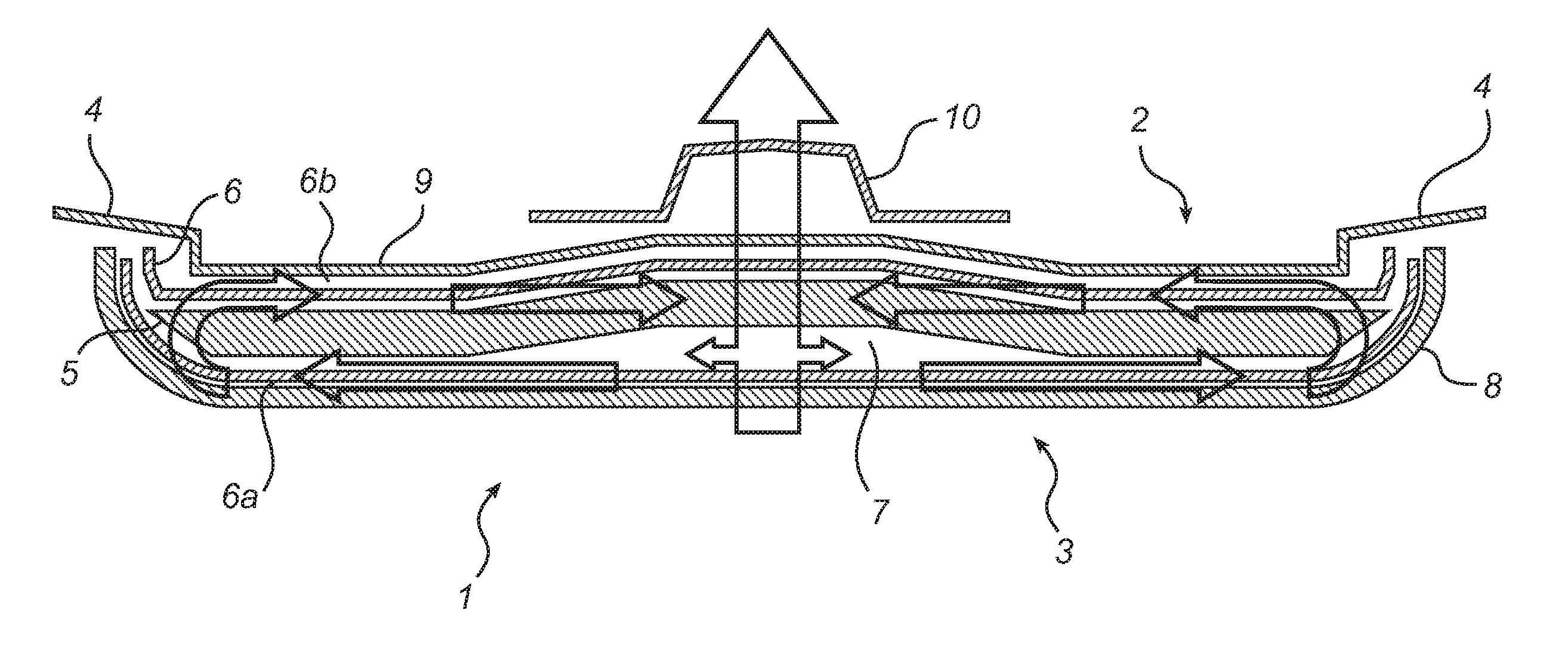
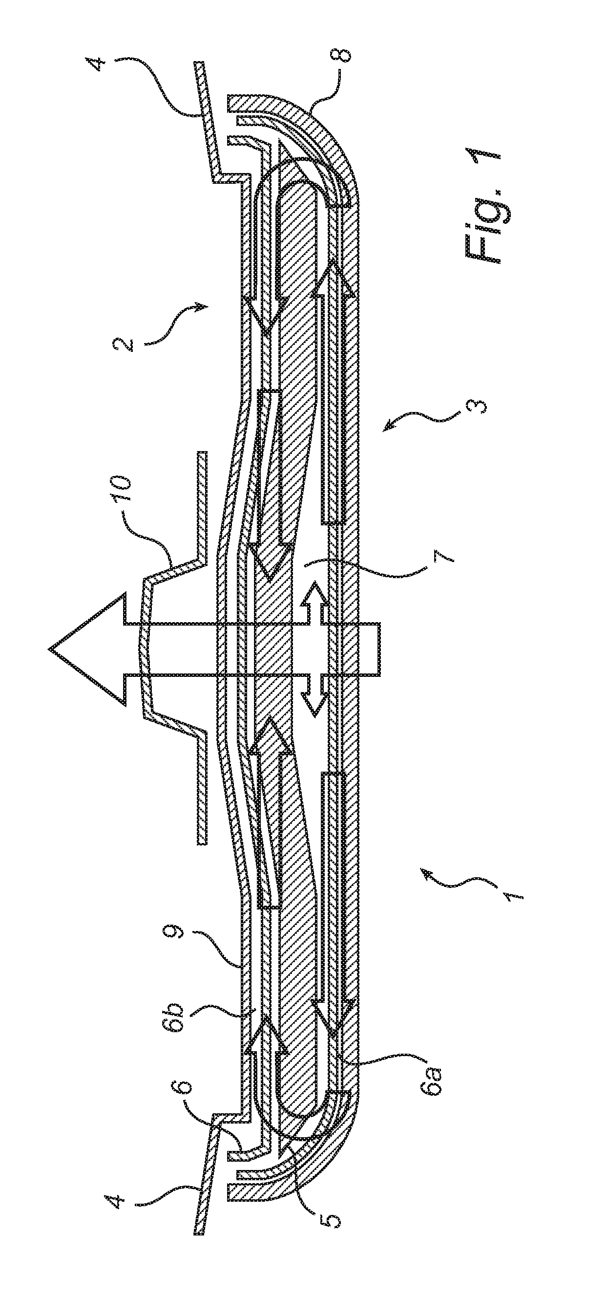
[0038]With reference to FIG. 1, the present invention relates to a pre-consolidated laminate pre-form 1 having a top side 2 and a back side 3 extending between respective edge portions 4.

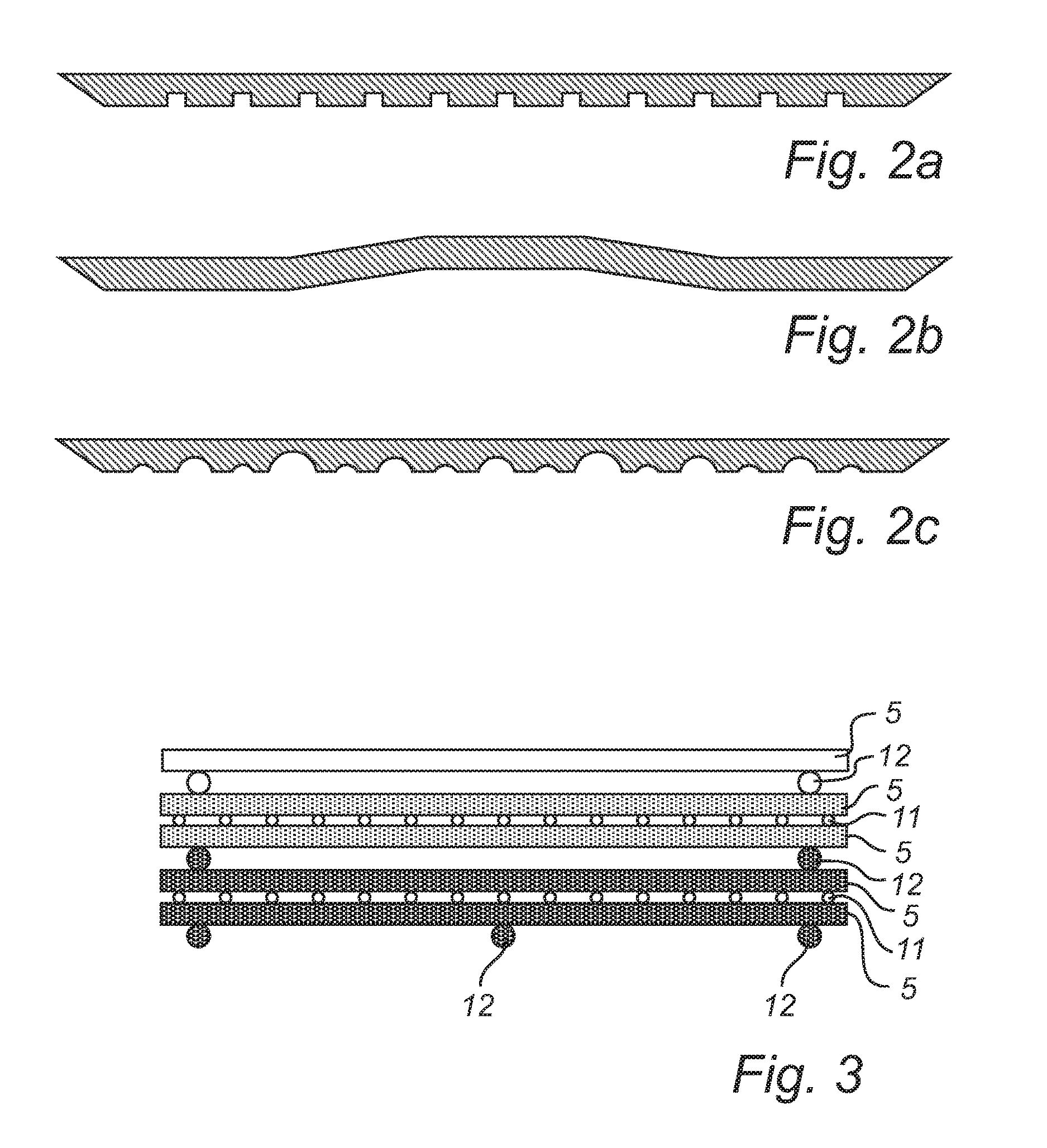
[0039]The laminate pre-form 1 comprises a plurality of layers of fibre tows 5 extending in a length direction of said laminate pre-form 1.

[0040]Different types of fibres, such as glass fibres, carbon fibres, synthetic fibres, bio fibres, mineral fibres, and metal fibres can be used depending on the final use of the pre-form. For reinforcing a large composite structure, which is subject to significant stress, such as a wind turbine blade spar, carbon fibres are preferred, since they are much stronger than e.g. glass fibres. The pre-form comprises fibres in fibre tows which are bundles of a large number of individual fibres, i.e. bundles of unidirectional fibres.

[0041]Each fibre tow may comprise fibres which are twisted in a manner known, e.g. from rope making etc., or may comprise fibres arranged sid...


PUM

PropertyMeasurementUnit
porosityaaaaaaaaaa
radiusaaaaaaaaaa
diameteraaaaaaaaaa

Abstract

A laminate preform is disclosed, having a top side and a back side extending between respective edge portions, the laminate preform comprising a plurality of layers of fiber tows extending in a length direction of the laminate pre-form, the fiber tows being at least partly fixed by resin. The laminate pre-form is in between a first and a second prepreg or semi-preg layer including fibers extending in an oblique direction with respect to the length direction, and at least one distribution channel is provided at the back side extending in the length direction. Also disclosed is a method for manufacturing such a laminate pre-form.

Description

TECHNICAL FIELD[0001]The present invention relates to a laminate pre-form for a wind turbine blade, comprising fibres and a fixing resin, for reinforcing a composite structure. The invention also relates to a method of producing such a pre-form.BACKGROUND OF THE INVENTION[0002]Composite structures, such as wind turbine blades, usually comprise a plurality of layers of sheets made of fibres embedded in a resin. These semi-finished component can be called pre-forms.[0003]Traditionally, such preforms have been produced by cutting layers of sheets from an endless sheet material of fibres in a resin, and stacking them in layers on each other to form a composite structure. The composite structure is then consolidated by removal of any air trapped between the layers of the structure, usually by applying a vacuum. During this consolidation procedure, additional resin may be introduced to, or infused in, the structure to fill any voids therein to strengthen the structure.[0004]Air trapped in...

Claims


Application Information

Patent Timeline
Patent Type & Authority Patents(United States)
IPC IPC(8): B29D99/00B29C70/54F01D5/28B29C70/46
CPCB29D99/0025B29C70/465B29C70/547F01D5/282Y02P70/523Y10T428/24124Y02P70/50F03D1/0675
Inventor RICHTER, JED
Owner VESTAS WIND SYST AS
Why Eureka
Try Eureka