Physical quantity detecting device and electric power steering apparatus using same
a technology of physical quantity and detecting device, which is applied in the direction of instruments, force/torque/work measurement apparatus, transportation and packaging, etc., can solve the problem of detection of abnormal torque sensor, and achieve the effect of accurate detection of signal transmission abnormality of transmission system and improving reliability of physical quantity detecting devi
- Summary
- Abstract
- Description
- Claims
- Application Information
AI Technical Summary
Benefits of technology
Problems solved by technology
Method used
Image
Examples
first embodiment
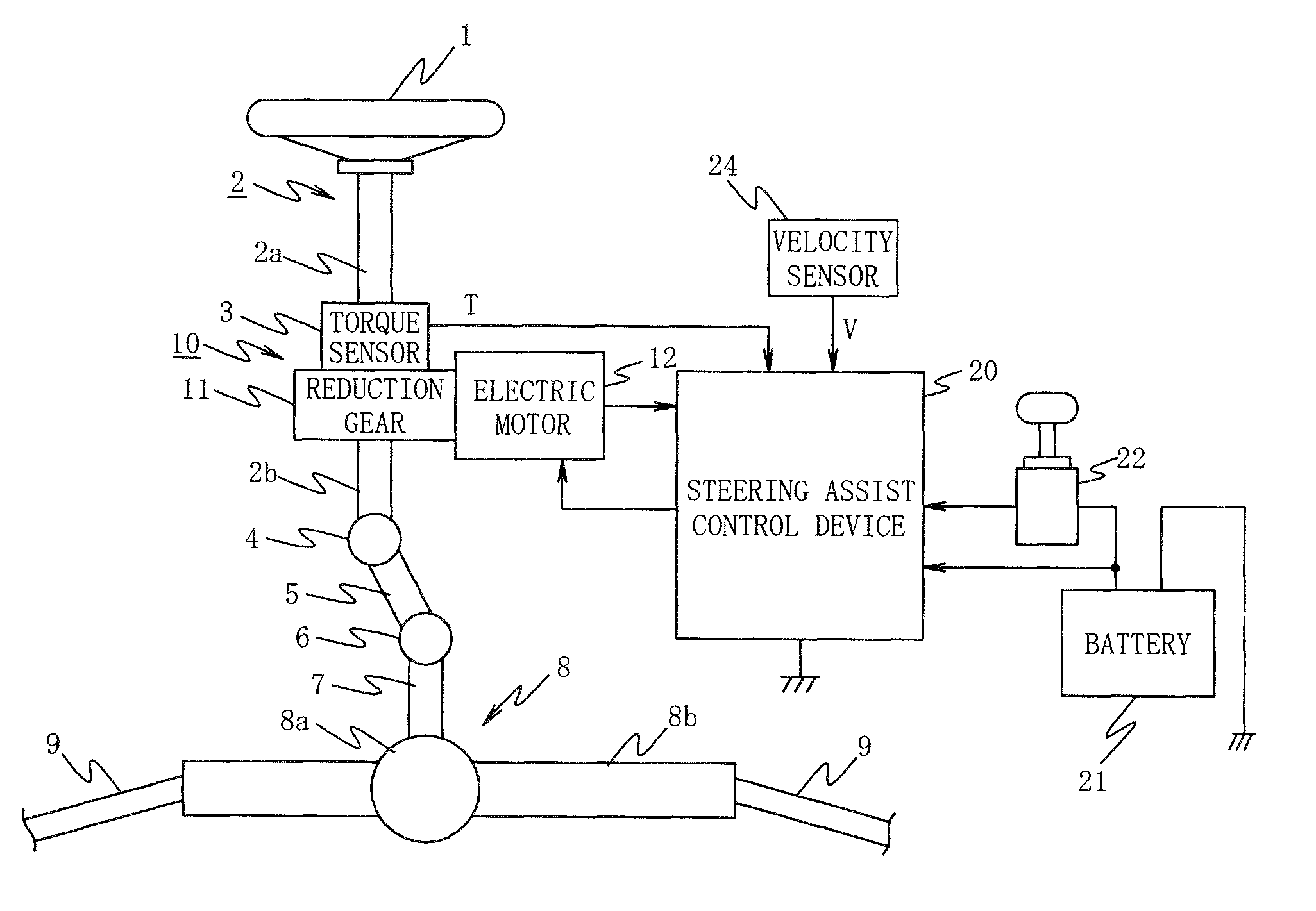
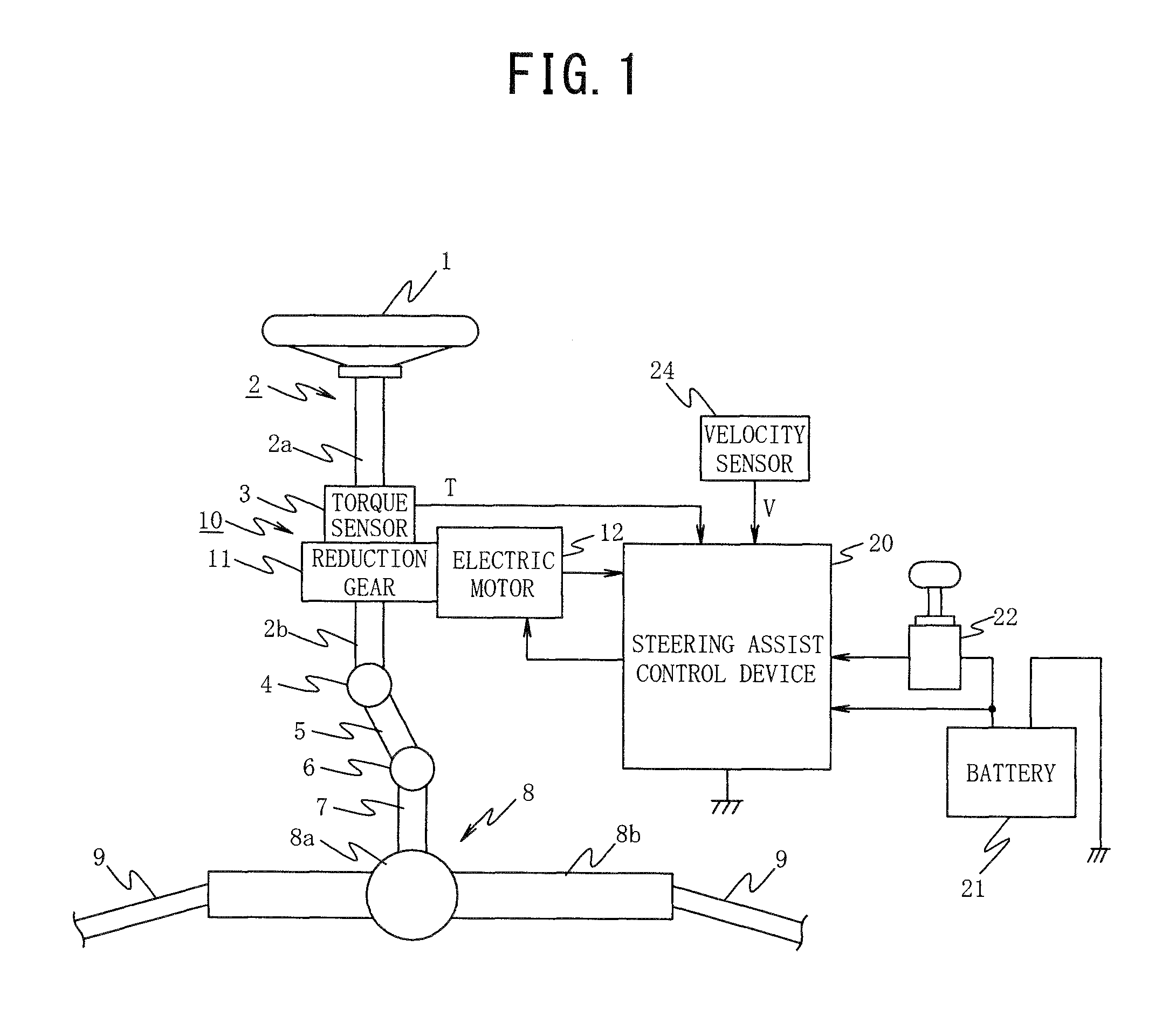
[0033]FIG. 1 is a diagram illustrating an example of the whole configuration of an electric power steering apparatus according to the present invention.
[0034]In the electric power steering apparatus, a steering effort which is applied to a steering wheel 1 by a driver is transmitted to a steering shaft 2 including an input shaft 2a and an output shaft 2b. One end of the input shaft 2a of the steering shaft 2 is linked to the steering wheel 1 and the other end is linked to one end of the output shaft 2b via a torque sensor 3 as a detection unit of a physical quantity detecting device.
[0035]The steering effort transmitted to the output shaft 2b is transmitted to a lower shaft 5 via a universal joint 4 and is then transmitted to a pinion shaft 7 via a universal joint 6. The steering effort transmitted to the pinion shaft 7 is transmitted to tie rods 9 via a steering gear 8 to turn steered wheels not illustrated. Here, the steering gear 8 employs a rack-and-pinion type including a pinio...
second embodiment
[0107]the present invention will be described below with reference to FIG. 5.
[0108]In the second embodiment, the steering assist control device 20 can request the torque sensor 3 to transmit a diagnostic signal.
[0109]That is, in the second embodiment, a signal transmission line 41 for transmitting a diagnostic signal transmission request signal is provided between the micro control unit 31 of the steering assist control device 20 and the calculating unit 3c of the torque sensor 3 as illustrated in FIG. 5.
[0110]In the signal switching process which is performed by the calculating unit 3c of the torque sensor 3, step S31 is performed after step S9 as illustrated in FIG. 6. In step S31, it is determined whether or not the diagnostic signal transmission request signal is received from the micro control unit 31 of the steering assist control device 20 is performed.
[0111]When it is determined in step S31 that the diagnostic signal transmission request signal is not received, the process r...
third embodiment
[0119]the present invention will be described below with reference to FIGS. 8 and 9.
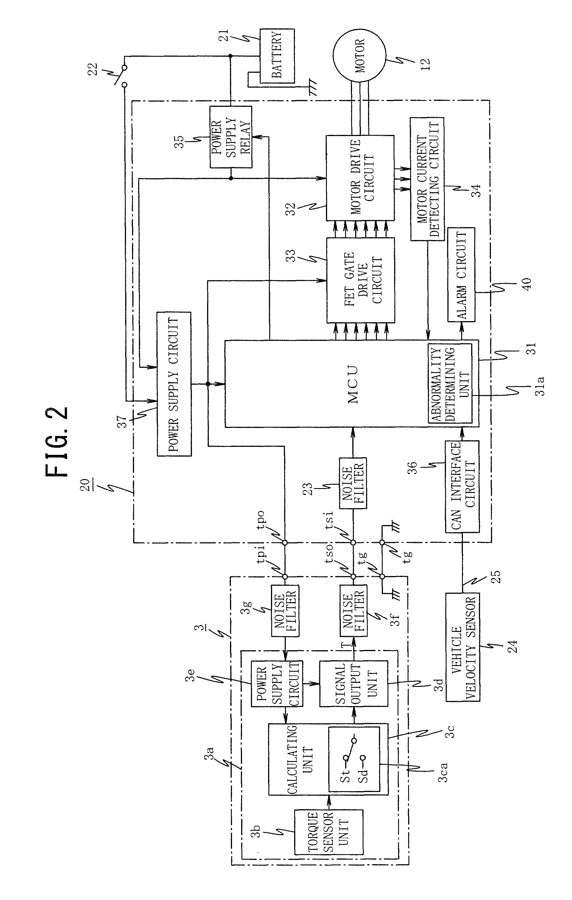
[0120]In the third embodiment, the abnormality of the noise filters 3f and 23 interposed between the torque sensor unit 3a of the torque sensor 3 and the micro control unit 31 of the steering assist control device 20 is detected.
[0121]That is, in the third embodiment, the abnormality determining unit 31a of the micro control unit 31 illustrated in FIG. 2 in the first embodiment is used to detect the abnormality of the noise filters 3f and 23.
[0122]That is, the micro control unit 31 performs a steering assist control process illustrated in FIG. 8.
[0123]The steering assist control process includes step S50. In step S50, a diagnostic signal receiving process is performed instead of the processes of steps S13 and S14 in the steering assist control process illustrated in FIG. 4.
[0124]In the diagnostic signal receiving process of step S50, as illustrated in FIG. 9, it is first determined in step S51 whethe...
PUM
| Property | Measurement | Unit |
|---|---|---|
| internal voltage | aaaaa | aaaaa |
| internal voltage | aaaaa | aaaaa |
| voltage | aaaaa | aaaaa |
Abstract
Description
Claims
Application Information
 - R&D
- Intellectual Property
- Life Sciences
- Materials
- Tech Scout
- Unparalleled Data Quality
- Higher Quality Content
- 60% Fewer Hallucinations
Browse by: Latest US Patents, China's latest patents, Technical Efficacy Thesaurus, Application Domain, Technology Topic, Popular Technical Reports.
© 2025 PatSnap. All rights reserved.Legal|Privacy policy|Modern Slavery Act Transparency Statement|Sitemap|About US| Contact US: help@patsnap.com


