
Native version alignment devices and methods

a technology of applied in the field of native version alignment devices and methods, can solve problems such as joint dislocation, soft tissue imbalance, and increased wear

Inactive Publication Date: 2017-02-21
ROSS MATTHEW S
View PDF4 Cites 0 Cited by
  • Summary
  • Abstract
  • Description
  • Claims
  • Application Information

AI Technical Summary

Benefits of technology

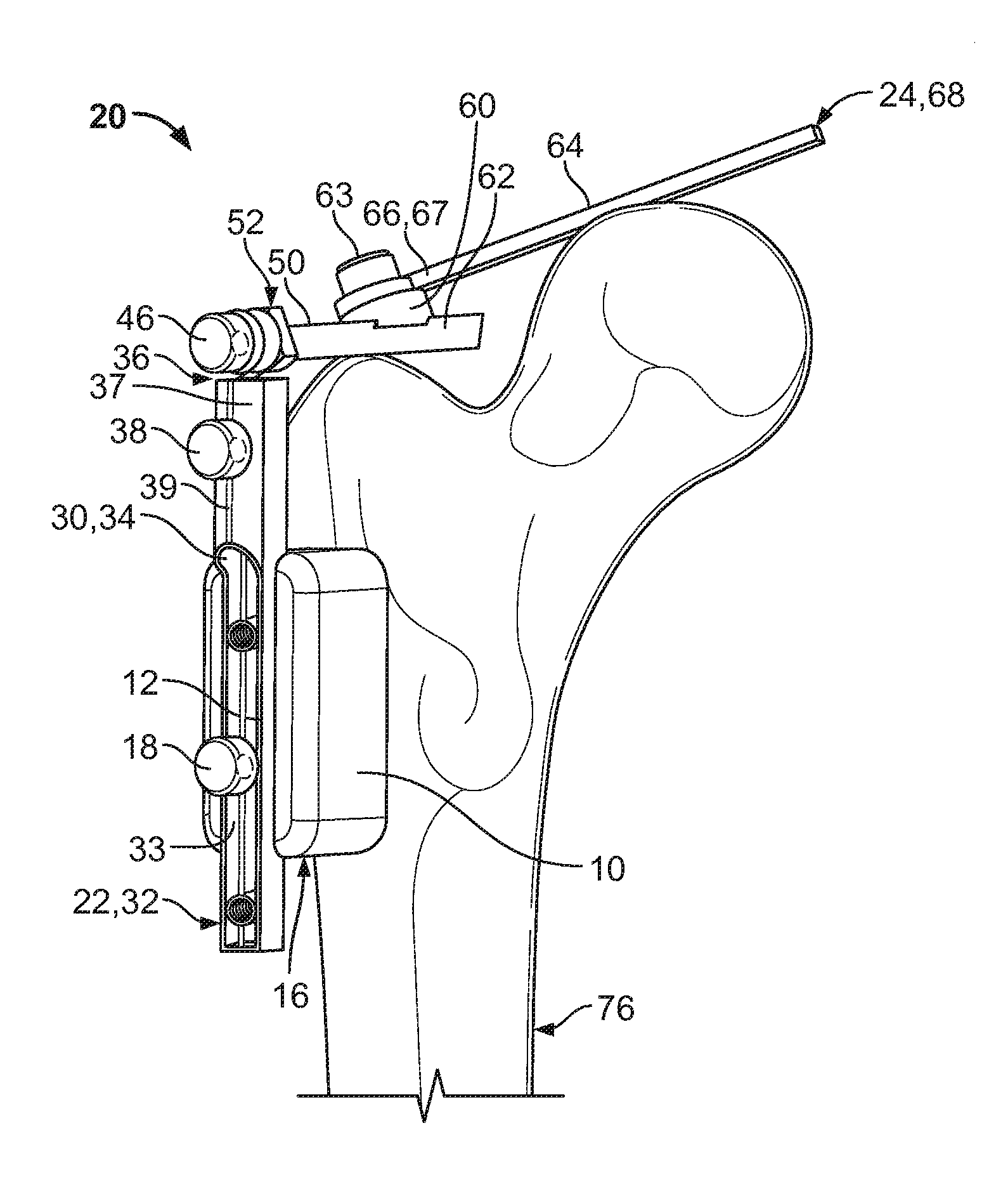
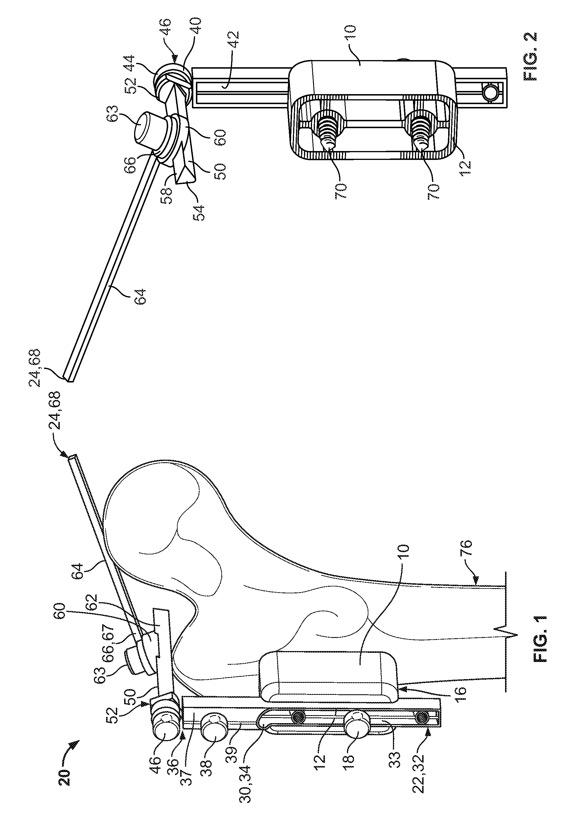
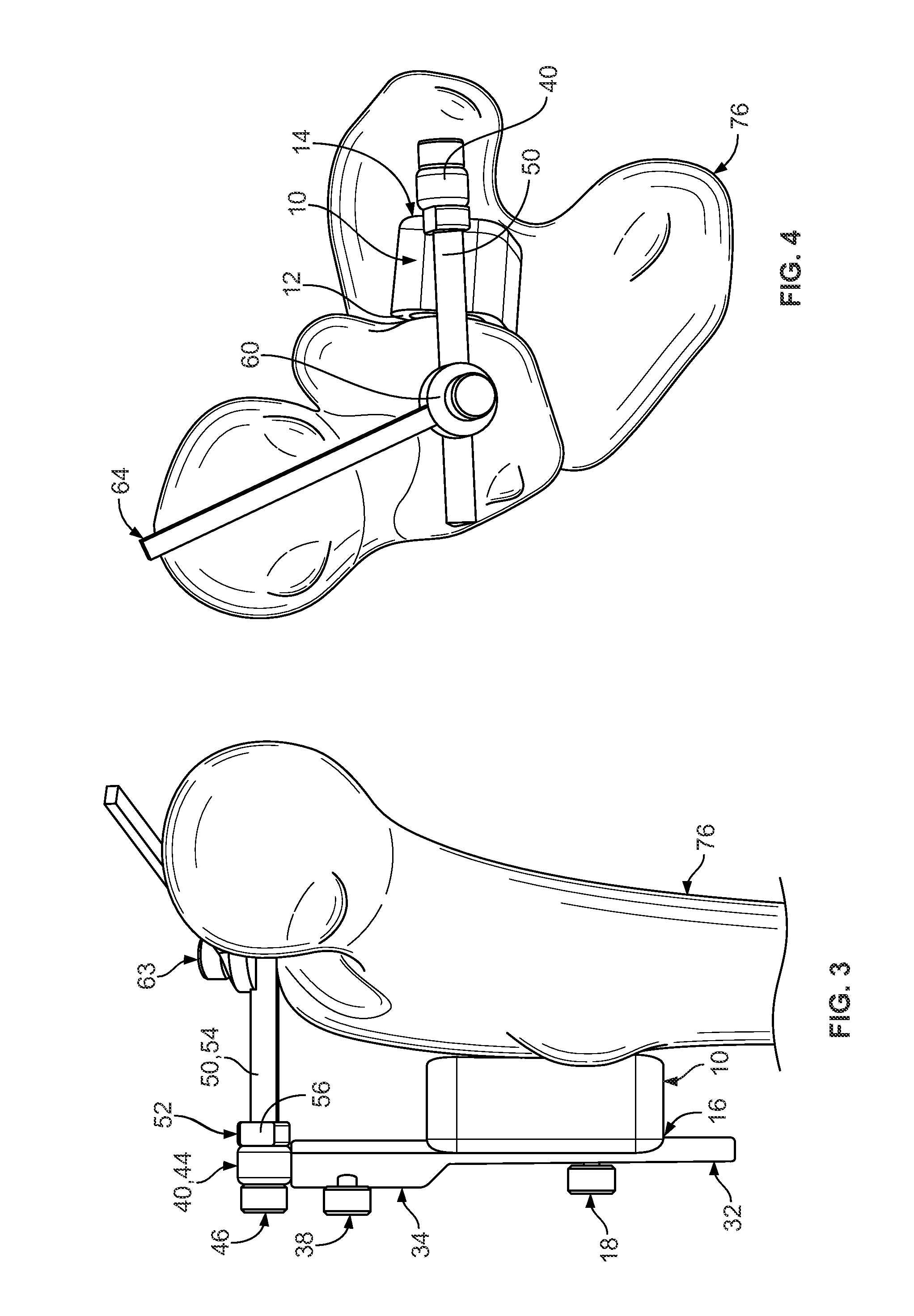
[0006]An example may be a surgical device for properly aligning a prosthesis to the native version alignment of a bone and comprising a base plate, an alignment arm and one or more fasteners for securing the base plate to the existing bone. The base plate has an outer surface and an underside surface such that the underside surface attaches to the bone and the outer surface faces away from the bone. The alignment arm has a proximal end and a distal end. The proximal end adjustably attaches to the outer surface of the base plate by a second fastener or fasteners. The alignment arm may be detached and removed from the base plate. The distal end of the alignment arm adjusts in 3-dimensions to assist in determining the proper alignment position for a prosthesis.

Problems solved by technology

Proper alignment of the implanted prosthesis is critical to the long term success of the implantation, and improper positioning can cause instability, impingement and increased wear.
Misalignment of a prosthesis can also lead to soft tissue imbalance, joint dislocation, compromised range of motion and increased pain to the patient.
However, the utility of computer-aided navigation systems has not been fully explored, and the technique is expected to increase surgical times, particularly with medical professionals new to such technology.
Preoperative CT scans can also be used to determine the proper alignment, but use of this technique results in increased radiation exposure to the patient, which is undesirable.
Some mechanical devices to align prosthetic implants exist, but these devices rely on the statistical average range of alignment values based on the anatomical studies and do not account for the full range of variability.
These devices do not re-create the native alignment and, therefore, often result in misalignment leading to the aforementioned consequences.

Method used


Image

  • Native version alignment devices and methods
  • Native version alignment devices and methods
  • Native version alignment devices and methods

Examples


Embodiment Construction

[0024]In the following detailed description, reference is made to the accompanying drawings, which form a part hereof. In the drawings, similar symbols typically identify similar components, unless context dictates otherwise. The illustrative examples described in the detailed description, drawings, and claims are not meant to be limiting. Other examples may be utilized, and other changes may be made, without departing from the spirit or scope of the subject matter presented here. It will be readily understood that the aspects of the present disclosure, as generally described herein, and illustrated in the Figures, may be arranged, substituted, combined, and designed in a wide variety of different configurations, all of which are explicitly contemplated and make part of the present disclosure.

[0025]The present disclosure is generally directed to a surgical device for properly aligning a prosthesis to the native version alignment and methods of aligning a prosthesis. Some example sur...


PUM


Abstract

Devices and methods for aiding practitioners in the implementation of arthroplasty prosthetics. Example devices may include a base and an alignment arm, and may be used for finding and recording the native alignment of a bone head, such as the femoral or humeral head. The base may be attached to the bone and the alignment arm may be adjusted to reflect the native alignment of the bone. Once the alignment is recorded, the native bone head may be removed and the prosthetic bone head may be attached to the bone, and properly oriented using the alignment arm of the device.

Description

CROSS REFERENCE TO RELATED APPLICATIONS[0001]This application claims the benefit of U.S. Provisional Patent Application Ser. No. 61 / 805,752, titled “Native Version Alignment Device,” filed on Mar. 27, 2013, the disclosure of which is incorporated herein by reference. This application also claims the benefit of U.S. Provisional Patent Application Ser. No. 61 / 811,615, titled “Native Version Alignment Device,” filed Apr. 12, 2013, the disclosure of which is incorporated herein by reference.BACKGROUND[0002]Prosthetic bone implantation and joint replacement is well known in the art. Proper alignment of the implanted prosthesis is critical to the long term success of the implantation, and improper positioning can cause instability, impingement and increased wear. Misalignment of a prosthesis can also lead to soft tissue imbalance, joint dislocation, compromised range of motion and increased pain to the patient.[0003]Having been in use since the mid-20th century, a conventional method of a...

Claims


Application Information

Patent Timeline
Patent Type & Authority Patents(United States)
IPC IPC(8): A61F2/46A61B17/88A61F2/40A61B17/56A61B17/68A61B17/90A61F2/36
CPCA61F2/4657A61B17/56A61B17/88A61B90/06A61F2/40A61F2/46A61B2017/564A61B2017/681A61B2017/90A61B2090/061A61B2090/067A61F2/36A61F2002/4658A61F2002/4668A61B17/90
Inventor ROSS, MATTHEW S.
Owner ROSS MATTHEW S
Learn More