
Compact optical spectrometer

a compact, optical technology, applied in the direction of optical radiation measurement, instruments, spectrometry/spectrophotometry/monochromators, etc., can solve the problems of difficult production, difficult to produce, and difficult to move optical elements with complex precision machinery, etc., to achieve compact and robust

Active Publication Date: 2017-02-14
WISCONSIN ALUMNI RES FOUND
View PDF10 Cites 24 Cited by
  • Summary
  • Abstract
  • Description
  • Claims
  • Application Information

AI Technical Summary

Benefits of technology

[0010]The present invention provides an analyzing filter system for a spectrometer that provides a set of uncorrelated and varying filter spectra over an extremely short optical path. Although the filter spectra are complex and appear largely random, they can be assembled into absorption spectrum mathematically, for example, by compressed sensing techniques. The result is a spectrometer that can be both compact and robust.
[0014]It is thus a feature of at least one embodiment of the invention to provide a frequency filter that provides an efficient analysis of a received light signal with a reduced number of different filter spectra.

Problems solved by technology

This sinusoidal spectrum is generated by reflecting a broadband light beam back on itself so that the light is subject to constructive and destructive interference at different frequencies.
Both of these types of spectrometers require relatively large optical paths for good resolution and may further require complex precision machinery to move optical elements during the measurement process.
As a result, low-cost and compact spectrometers, potentially useful in a variety of applications, are difficult to produce.

Method used


Image

  • Compact optical spectrometer
  • Compact optical spectrometer
  • Compact optical spectrometer

Examples


Embodiment Construction

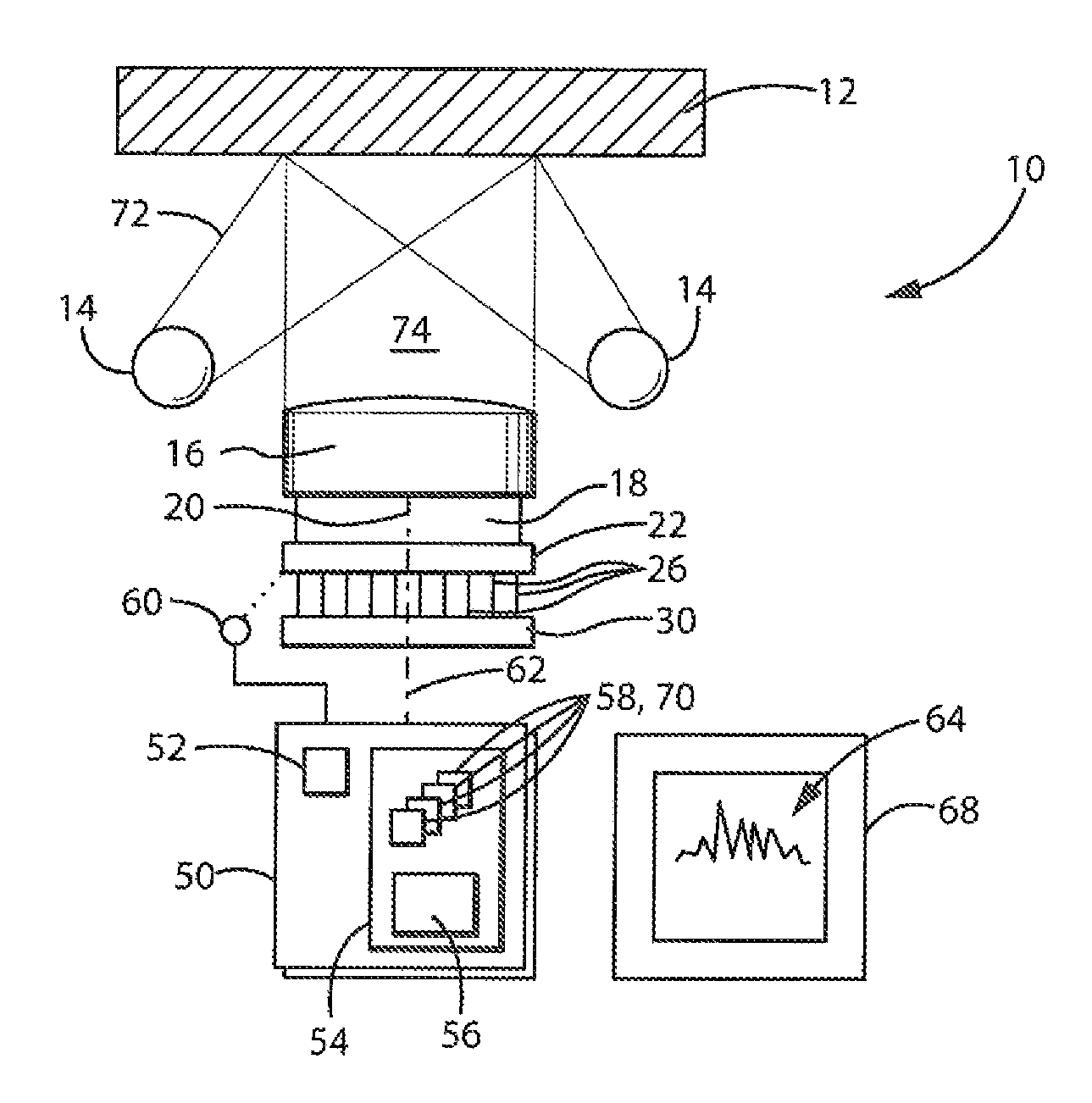
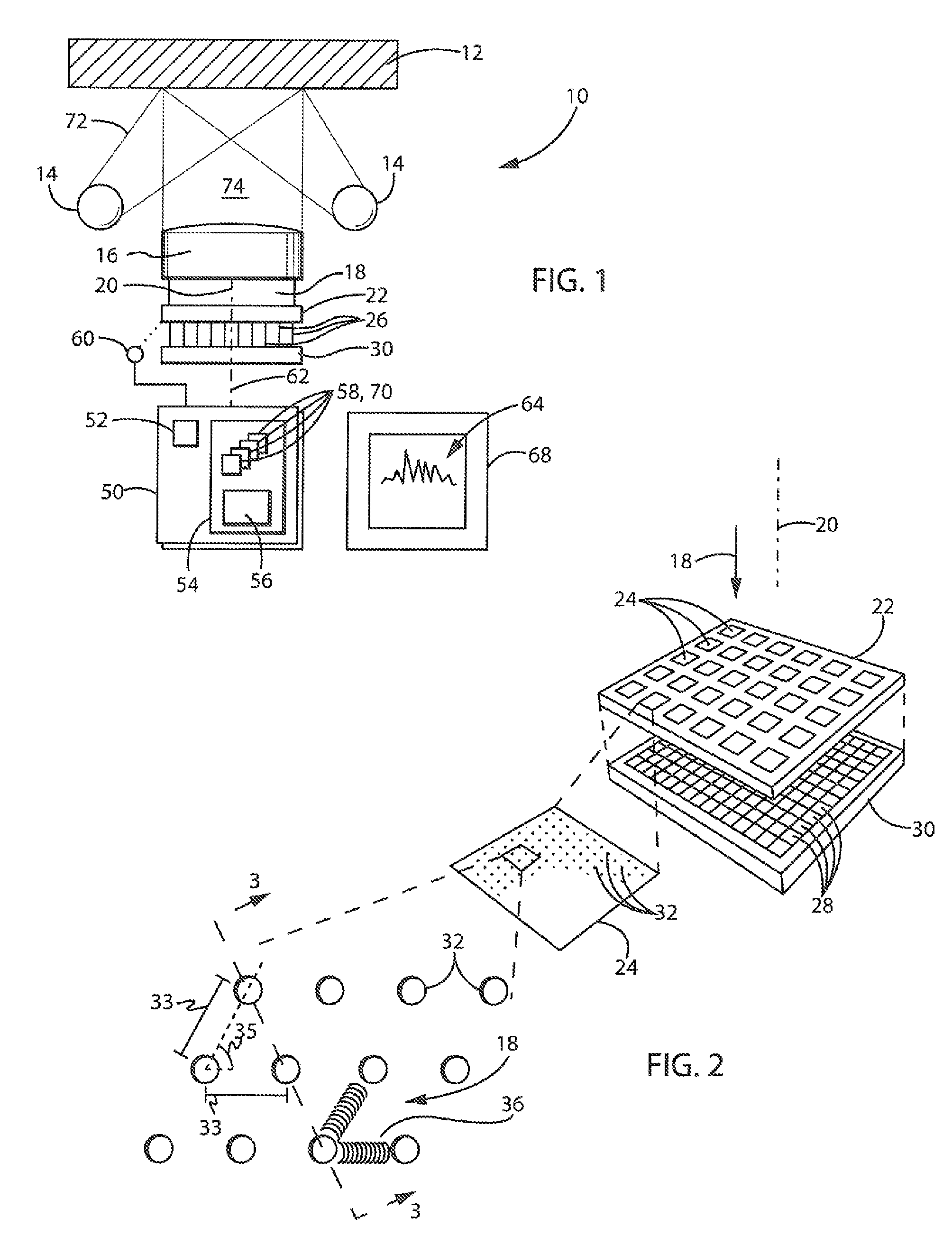
[0041]Referring now to FIG. 1, a spectrometer 10 of the present invention may be configured to make absorption spectrographic measurements of a sample material 12. In this configuration, one or more light sources 14 having a known spectral output, for example, light emitting diodes or incandescent bulbs, may shine a light on the sample material 12 to be reflected into a collimator 16. It will be understood that in a minor variation on this arrangement, the light sources 14 may be positioned to transmit light through the sample material 12.

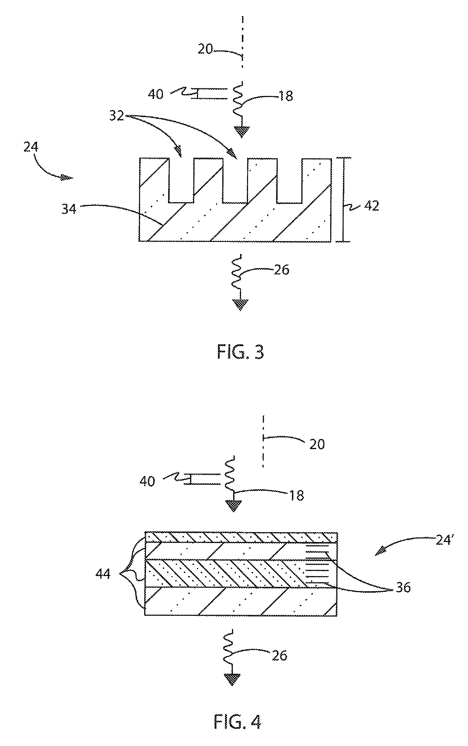
[0042]Light from the collimator is directed as a received light beam 18 generally along axis 20 normal to the surface of a generally planar frequency-filter plate 22. The frequency-filter plate 22 may have a set of filter elements 24, for example, in square tiles arranged in rows and columns over the two-dimensional area of the planar frequency-filter plate 22. Each of these filter elements 24 will have a different filter spectrum, being a descript...


PUM


Abstract

A spectrometer employs multiple filters having complex filter spectra that can be generated robustly from received light over short optical path lengths. The complex filter spectra provide data that can be converted to a spectrum of the received light using compressed sensing techniques. The result is a more compact, easily manufactured spectrometer.

Description

STATEMENT REGARDING FEDERALLY SPONSORED RESEARCH OR DEVELOPMENT[0001]Not ApplicableCROSS REFERENCE TO RELATED APPLICATION[0002]Not ApplicableBACKGROUND OF THE INVENTION[0003]The present invention relates to systems for measuring light spectra, for example, for absorption, transmission, or reflection spectroscopy, and in particular to an optical spectrometer providing compact and robust construction.[0004]Optical spectrometers provide a measurement of light intensity over multiple frequencies. An optical spectrometer may measure the spectrum of an unknown light source or be used with a known light source to measure absorption of a material when light from the known light source passes through or is reflected from the measured material before being detected. This latter absorption spectrum is derived by subtracting the spectrum of the light received at the detector from the spectrum of the known light source.[0005]Distinguishing the intensity of different frequencies of light, as need...

Claims


Application Information

Patent Timeline
Patent Type & Authority Patents(United States)
IPC IPC(8): G01J3/02G01J3/28G01J3/12G01J3/42G01J3/26
CPCG01J3/28G01J3/12G01J3/42G01J3/26G01J2003/1213G01J2003/1239G01J2003/1282G01J2003/2806
Inventor YU, ZONGFU
Owner WISCONSIN ALUMNI RES FOUND
Learn More