Device for and method of connecting two items together
a technology of two items and a connection method, applied in the direction of key-type connection, sheet joining, rod connection, etc., to achieve the effect of large surface area, large surface area, and bringing into engagement with the other
- Summary
- Abstract
- Description
- Claims
- Application Information
AI Technical Summary
Benefits of technology
Problems solved by technology
Method used
Image
Examples
first embodiment
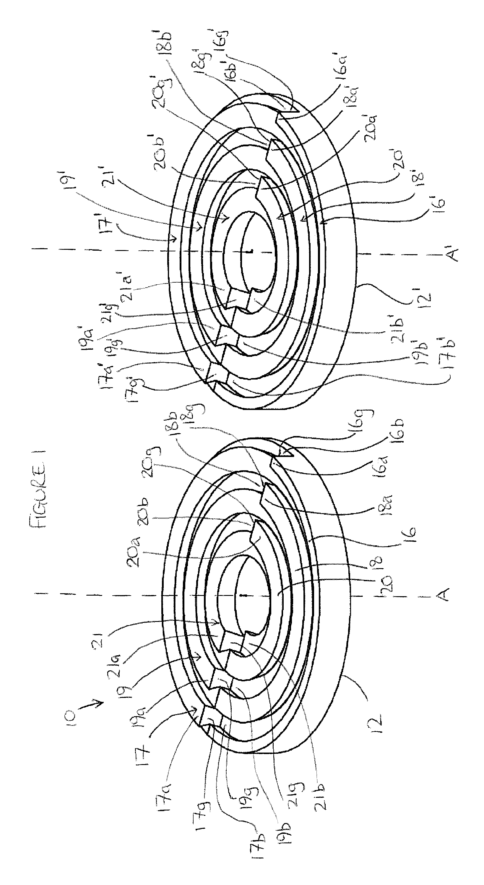
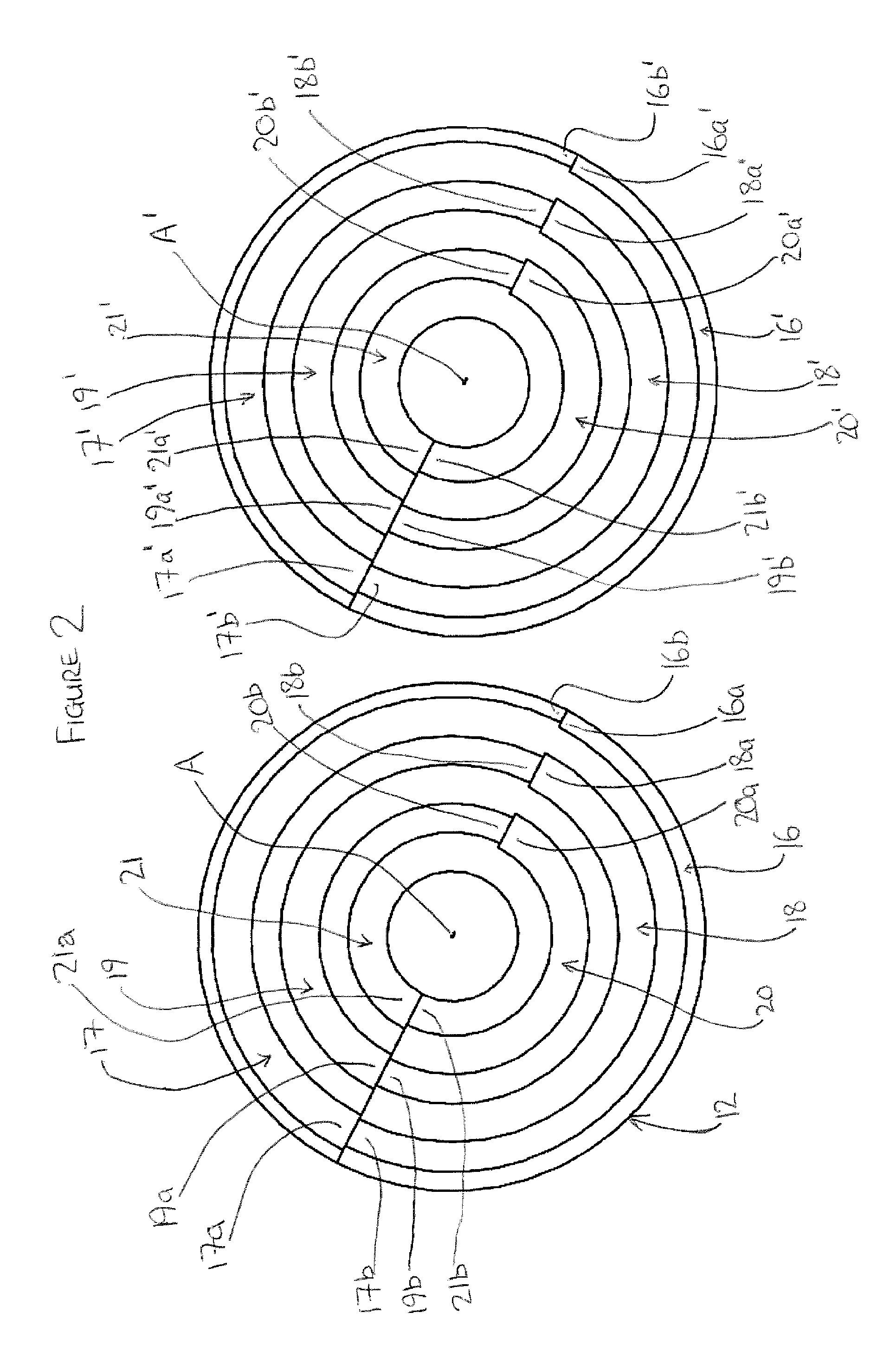
[0063]Referring to FIG. 1, there is shown the invention. A connector 10 includes a first part 12 and a second part 12′. In this embodiment of the invention, the first part and the second part are identical to one another. The first part 12 and the second part 12′ each includes a plurality of engagement formations, 16, 17, 18, 19, 20 and 21, and the second part 12′ includes a plurality of engagement formations 16′, 17′, 18′, 19′, 20′ and 21′, Whilst in the example described herein, each part 12, 12′ includes six engagement formations 16-2116′-21′, any number of engagement formations, including one, may be provided—Each of the engagement formations 16-21 and 16-21′ is substantially annular and has a first end 16a, 17a, 18a, 19a, 20a, 21a, 16a′, 17a′, 18a′, 19a′, 20a′, 21a″, and a second end 16b, 17b, 18b, 19b, 20b, 21b, 22b, 16b′, 17b′, 18b′, 19b′, 20b′ and 21b′. Each engagement formation 16-21, 16′-21′ has a first portion which extends between the first end 16a-21a, 16a′-21a′ of the ...
second embodiment
[0081]the invention 110 is shown in FIGS. 5 to 7. The connector 110 is similar to the connector 10, and similar features are referenced with similar reference numerals, prefixed with “1”. The connector 110 is an example of a “quadruple pick-up”, 90° rotation connector.
[0082]The connector 110 includes two parts 112 and 112′. The two parts 112 and 112′ are not identical, but are engageable with one another. Each part 112, 112′ has a respective connecting face which is substantially transverse to a longitudinal axis B, B′ of the respective part 112, 112′.
[0083]The first part includes a plurality of engagement formations 116, 117, 118, 119. The engagement formations 116-119 are substantially annular, and are concentric about a longitudinal axis B. Each engagement formation 116-119 extends axially, in a direction which is substantially parallel to the longitudinal axis B. Each engagement formation 116-119 is separated from an adjacent engagement formation by a receiving formation 120, 12...
third embodiment
[0097]the invention is shown in FIGS. 8 to 10. A connector 210 includes two parts 212, 212′. The first part 212 includes a plurality of engagement formations 216, 217, 218, 219, 220. The engagement formations 216-220 are substantially annular and concentric about a longitudinal axis C. Each engagement formation 216-220 includes two sectors X, Y. However, each part 212, 212′ may have any number of sectors. Each sector X, Y has a first end, a second end, an upper surface, and a lower surface. Each sector X, Y of each engagement formation 216-220 also includes an inner circumferential wall and an outer circumferential wall which, together, form two substantially circular side walls. The upper surface of each sector X, Y of each engagement formation 216-220 is substantially helicoidal. Each sector X, Y of each engagement formation 216-220 includes an end face which is positioned at the first end of the sector X, Y, and which is generally transverse to the side walls and the upper surfac...
PUM
| Property | Measurement | Unit |
|---|---|---|
| Fraction | aaaaa | aaaaa |
| Angle | aaaaa | aaaaa |
| Angle | aaaaa | aaaaa |
Abstract
Description
Claims
Application Information
 - R&D
- Intellectual Property
- Life Sciences
- Materials
- Tech Scout
- Unparalleled Data Quality
- Higher Quality Content
- 60% Fewer Hallucinations
Browse by: Latest US Patents, China's latest patents, Technical Efficacy Thesaurus, Application Domain, Technology Topic, Popular Technical Reports.
© 2025 PatSnap. All rights reserved.Legal|Privacy policy|Modern Slavery Act Transparency Statement|Sitemap|About US| Contact US: help@patsnap.com


