
Cable lacing tie devices and methods of using the same

a technology of cable lacing and tie, which is applied in the direction of buckles, flexible elements, packaging, etc., can solve the problems of increasing the tendency of the strap to tear through, reducing the strength of the strap, and generally not being able to closely hug irregular or rectangular shapes, so as to prevent abrasion against adjacent parts, the effect of rapid and secure installation

Active Publication Date: 2017-01-31
DANIELS MFG CORP
View PDF67 Cites 7 Cited by
  • Summary
  • Abstract
  • Description
  • Claims
  • Application Information

AI Technical Summary

Benefits of technology

The solution provides a lightweight, abrasion-resistant, and secure method for bundling cables with near-zero insertion force, enabling rapid and reliable installation in extreme temperature conditions, reducing the need for adhesives and minimizing material damage.

Problems solved by technology

However, such a barb or knife like strap piercing element is destructive to the strap when it cuts or bights into the strap, permanently reducing the strength of the strap and increasing the tendency for the strap to tear through.
However, the cut section of the molded plastic strap that protrudes from the buckle can present an undesirable, fairly sharp obstruction that may result in abrasion problems with respect to adjacent wire bundles, and may be problematic if one is attempting to pull the wire bundle through an aperture, such as a panel opening.
It should be noted that another drawback of molded plastic cable ties is that, due to their relative rigidity, they generally are not capable of closely hugging irregular or rectangular shapes, as may occur when bundling wires, wire harnesses or cables, or connecting them to other structures.
In the aerospace environment, a cable tie can be subjected to elevated temperatures as high as 400 degrees F. This can cause a common cable tie, which is typically molded from thermoplastic material, such as Nylon, to creep or lose structural integrity.
The locking element or pawl generally will be constructed to be deflectable, so as to reduce the strap insertion force, but this also compromises the ability to retain the strap, especially at high temperatures.
Cable ties that have a separately provided metal locking element or pawl usually are intended to provide for increased retention, even at elevated temperatures, but these structures typically require higher insertion forces when passing over the metal element.
Materials such as Nomex provide good tensile strength, while being non-flammable, highly resistant to fluids and lubricants, and able to perform in extreme temperature environments, such as from approximately −65 degrees F. to 500 degrees F. However, cable lacing has drawbacks in that the cable lacing tape typically is tied by hand in a costly, labor-intensive, and time-consuming process.
Such knot tying devices have their own drawbacks and one still is faced with using cable lacing tape that must be cut.
However, cutting the ends of the cable lacing tape may lead to the unraveling of the braided filaments.
The need to incorporate the use of adhesives or glues into the assembly method may present additional difficulties, such as for example cleanliness of the application, unintentional bonding of other objects or surfaces, and the introduction of potentially undesirable fumes, and / or flammable or incompatible fluids or materials.

Method used


Image

  • Cable lacing tie devices and methods of using the same
  • Cable lacing tie devices and methods of using the same
  • Cable lacing tie devices and methods of using the same

Examples


Embodiment Construction

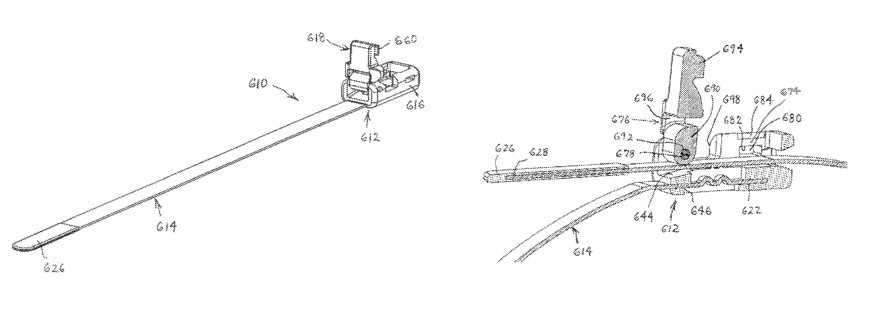
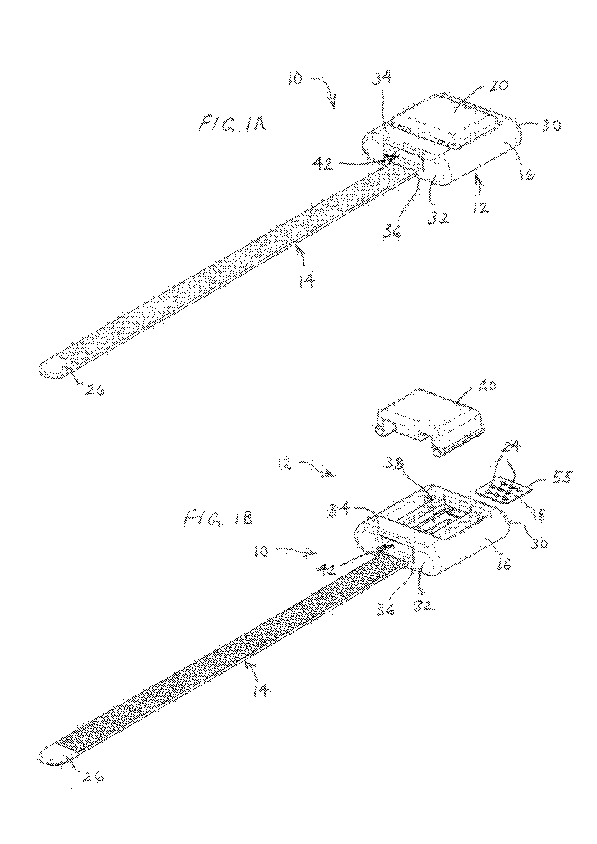
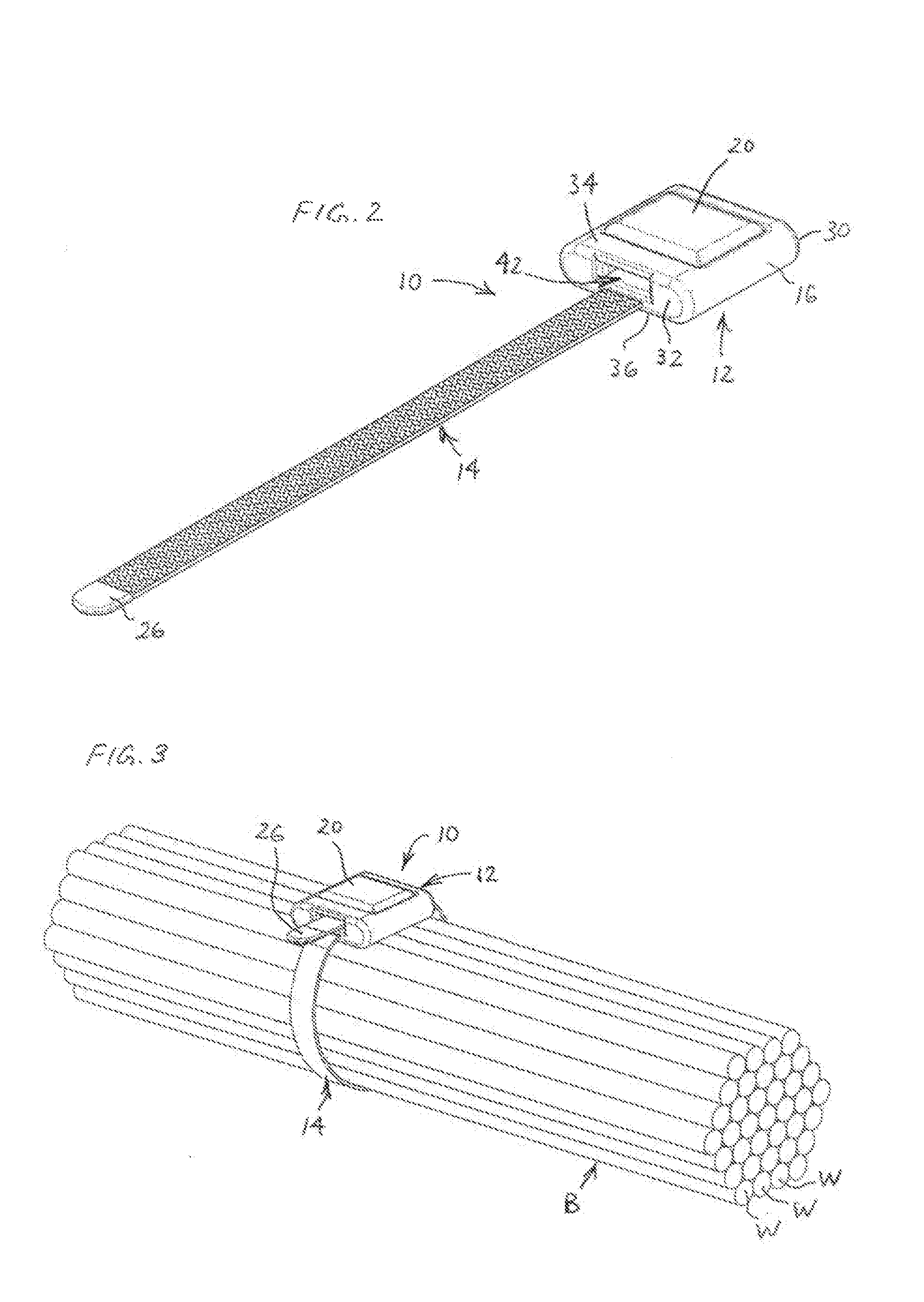
[0065]A first example cable lacing tie device 10 is illustrated in FIGS. 1A, 1B and 2-11. The cable lacing tie device 10 includes a head assembly 12 and a length of cable lacing tape 14. The head assembly 12 of this example includes a molded body 16, a retainer 18 in the form of a retainer plate, and a compression member 20. A first portion 22 of the cable lacing tape 14 is configured to be retained in a first position within the head assembly 12 by having a first end insert-molded within the body 16 in a tortuous path for enhanced retention, as best seen in FIG. 11. A length of the cable lacing tape 14 then extends from the front of the head assembly 12. The cable lacing tie device 10 may be used, for example, to hold together a plurality of objects, such as to form a bundle B of a group of wires W, which are shown in FIG. 3, in a simplified manner.

[0066]The body 16 and compression member 20 preferably each are injection molded and constructed of a material that is suitable for use...


PUM


Abstract

Cable lacing tie devices and methods of using the same are disclosed. The cable lacing tie devices include a head assembly and a cable lacing tape. The head assembly being configured to retain a first portion of the cable lacing tape within the head assembly and having a length of the cable lacing tape extending from the head assembly. The head assembly further adapted to retain a second portion of the cable lacing tape extending from the head assembly. The methods of using the cable lacing tie devices to hold together a plurality of objects with a cable lacing tie device include retaining a first portion of a cable lacing tape in a head assembly, looping the cable lacing tape around the plurality of objects and retaining a second portion of the cable lacing tape within the head assembly.

Description

CROSS REFERENCE TO RELATED APPLICATION[0001]This application is a divisional of U.S. patent application Ser. No. 13 / 269,828, filed Oct. 10, 2011, entitled “Cable Lacing Tie Devices and Methods of Using the Same,” which claims the benefit of U.S. Provisional Patent Application Ser. No. 61 / 391,851, filed Oct. 11, 2010, the disclosure of each are hereby incorporated by reference in their entirety.FIELD OF THE DISCLOSURE[0002]The present description relates generally to cable lacing ties and methods of using the same.BACKGROUND OF RELATED ART[0003]This disclosure relates to devices and methods for holding together two or more wires, wire harnesses, cables or other objects, or for connecting such objects to other structures. More particularly, the disclosure relates to cable lacing tie assemblies for use in bundling a plurality of objects such as wires, wire harnesses, cables or other objects, and methods of using such cable lacing tie assemblies.[0004]Individual wires, wire harnesses or...

Claims


Application Information

Patent Timeline
Patent Type & Authority Patents(United States)
IPC IPC(8): B65D63/16A44B11/06B65D63/10
CPCB65D63/16A44B11/06B65D63/1063Y10T24/14Y10T24/1498
Inventor BREEN, IV, DENNIS M.ZANTOUT, ALAN E.PETERSON, THOMAS D.CRICHTON, PETER J.
Owner DANIELS MFG CORP
Learn More