Z-microscopy

a microscopy and z-microscopy technology, applied in the field of z-microscopy, can solve the problems of slow scanning, limiting the z-imaging speed, and affecting the ability to image fast processes in the axial direction, so as to achieve efficient signal reflection, large numerical aperture, and large field of view

Active Publication Date: 2017-01-17
PENN STATE RES FOUND
View PDF14 Cites 0 Cited by
  • Summary
  • Abstract
  • Description
  • Claims
  • Application Information

AI Technical Summary

Benefits of technology

[0008]Our method for parallel axial imaging, or z-microscopy, utilizes an array of tilted micro mirrors arranged along an axial direction of a probe. Typically the micro mirrors are placed at an angle of 45 degrees with respect to the axial direction, though they may be varied as desired. Image signals emitted from different axial positions can be orthogonally reflected by corresponding micromirrors and spatially separated for parallel detection, essentially converting the more challenging axial imaging to a lateral imaging problem. Each micro mirror also provides optical sectioning capability due to its finite dimension. Numerical analysis shows that nearly diffraction limited axial resolution can be achieved.
[0015]A further embodiment includes a device for analysis of the z-axis dimension of a sample, including a means for generation of a detection signal as discussed above. The means for generation of a detecting signal is directed to a sample, generating a detecting signal, and at least one collection lens is disposed to focus said detecting signal on a micromirror array. The device further includes at least one detection lens able to focus said detecting signal from said micromirror array; and it may include at least one detector array disposed to detect said detecting signal from said detection lens. Detection lenses may, for example, have a large enough numerical aperture to efficiently collect the signals reflected by the micro-mirrors, and large enough field of view to capture the signals from all the micro-mirrors in the desired axial imaging range.

Problems solved by technology

This hinders the ability to image fast processes in the axial direction.
However, slow scanning, particularly in the axial (or z) direction remains a hindrance.
This typically requires mechanical axial scanning of the specimen or the excitation objective lens, limiting the z-imaging speed and hence the ability to visualize fast dynamic processes in the axial slice plane and overall in the three dimensions.
However, these techniques lack optical sectioning capability.
However, parallel z-imaging has yet to be realized using wavelength division multiplexing in scanning fluorescence microscopy, one of the most widely used imaging modalities.
Although chromatic scanning can be utilized to accomplish effective axial scanning, the fluorescence signals excited at different axial positions exhibit similar emission spectra, preventing the use of parallel spectroscopic detection.

Method used


Image

  • Z-microscopy
  • Z-microscopy
  • Z-microscopy

Examples


Embodiment Construction

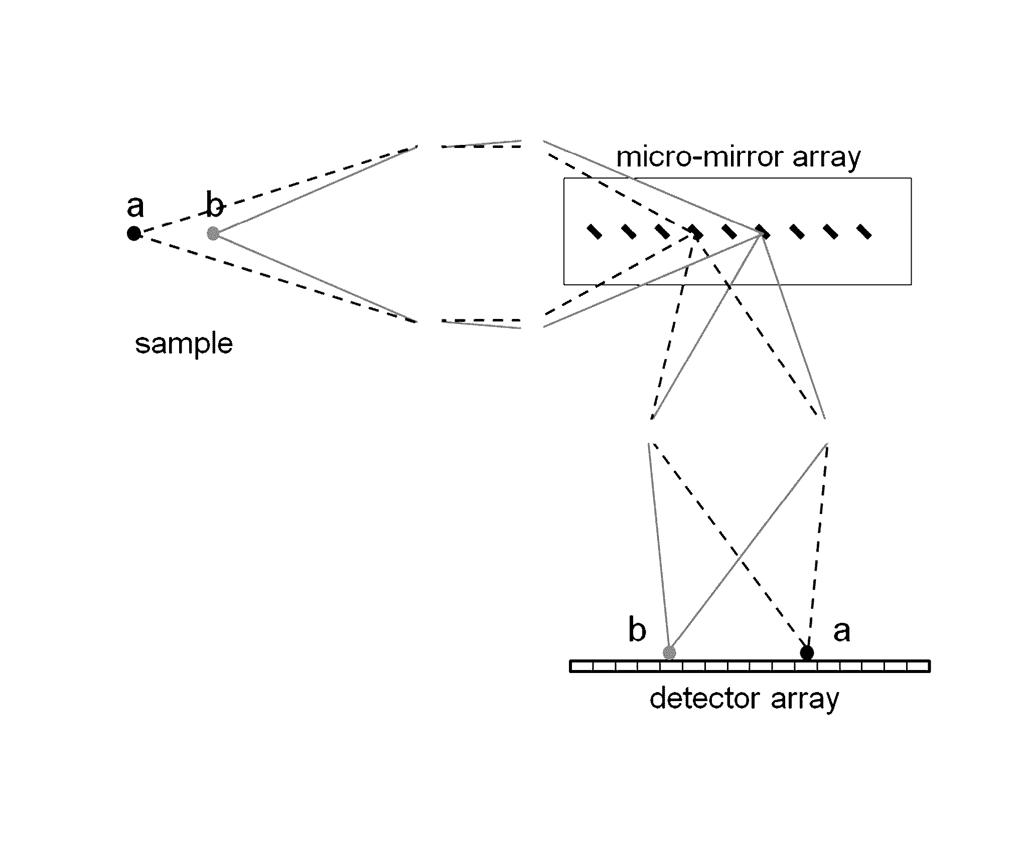
[0029]Embodiments of the invention relate to a new method for parallel axial imaging, also known as z-microscopy. We use a micro mirror array to de-multiplex image signals generated at different axial positions. Numerical analysis of the impulse response of the proposed imaging system validates the z-microscopy concept. The technique can be applied to multiple imaging modalities, including one-photon or multi-photon fluorescence microscopy, harmonic microscopy, confocal microscopy, and plane illumination light sheet microscopy. The vertical dimension of the micro mirror array can be further exploited to image a two-dimensional (2D) axial slice. The method can be particularly useful for studying fast phenomena in the axial direction and in three dimensions. As an example, later in this disclosure we demonstrate Z-imaging of multiple microspheres located at different axial positions.

[0030]To illustrate the demultiplexing concept, the diffraction of a converging wave by an array of mic...


PUM


Abstract

We present a method for parallel axial imaging, or z-microscopy, utilizing an array of tilted micro mirrors arranged along the axial direction. Image signals emitted from different axial positions can be orthogonally reflected by the corresponding micro mirrors and spatially separated for parallel detection, essentially converting the more challenging axial imaging to a lateral imaging problem. Each micro mirror also provides optical sectioning capability due to its finite dimension.

Description

CROSS-REFERENCE TO RELATED APPLICATIONS[0001]This application claims priority to U.S. Provisional Patent Application No. 61 / 730,701, filed on Nov. 28, 2012. That application is incorporated by reference herein.STATEMENT REGARDING FEDERALLY SPONSORED RESEARCH OR DEVELOPMENT[0002]This invention was made with government support under Grant No. DBI0649866, awarded by the National Science Foundation. The government has certain rights in the invention.BACKGROUND OF THE INVENTION[0003]There exists a conspicuous disparity in the lateral (i.e., x, y) and axial (i.e., z) imaging speed in conventional optical microscopy. While an image at the x-y plane can be routinely acquired in parallel or at high speed, slow mechanical scanning of the objective lens or the specimen itself is typically required in the z direction for axial imaging. This hinders the ability to image fast processes in the axial direction.[0004]Laser scanning optical microscopy, such as multi-photon and confocal microscopy, ha...

Claims


Application Information

Patent Timeline
Patent Type & Authority Patents(United States)
IPC IPC(8): G02B21/36G02B21/00
CPCG02B21/008G02B21/006
Inventor LIU, ZHIWENYANG, CHUANSHI, KEBINZHOU, MINGDAZHENG, SIYANGYIN, SHIZHUO
Owner PENN STATE RES FOUND
Why Eureka
Try Eureka