
Transient fault detection methods and systems

a fault detection and transient technology, applied in the direction of machines/engines, fluid-tightness measurement, instruments, etc., can solve the problems of affecting the proper functioning affecting the normal operation of the gas turbine engine, and the failure of the buffer air system in general

Active Publication Date: 2017-01-17
RTX CORP
View PDF6 Cites 4 Cited by
  • Summary
  • Abstract
  • Description
  • Claims
  • Application Information

AI Technical Summary

Benefits of technology

The patent text describes a method for detecting valve faults by measuring air pressure and comparing it to predetermined values. This can be done using a computer-based controller that measures air pressure and alerts an operator when there is a failure in the buffer air system. The technical effect of this patent text is to provide a reliable and early detection of valve failures, which can prevent damage and reduce downtime.

Problems solved by technology

Buffer air systems and mechanical systems in general may fail.
The failure of buffer air system valves may impede the proper functioning of the gas turbine engine, as well as systems the engine may power.

Method used


Image

  • Transient fault detection methods and systems
  • Transient fault detection methods and systems
  • Transient fault detection methods and systems

Examples


Embodiment Construction

[0016]The detailed description of various embodiments herein makes reference to the accompanying drawings, which show various embodiments by way of illustration. While these various embodiments are described in sufficient detail to enable those skilled in the art to practice the disclosure, it should be understood that other embodiments may be realized and that logical, chemical, electrical, and mechanical changes may be made without departing from the spirit and scope of the disclosure. Thus, the detailed description herein is presented for purposes of illustration only and not of limitation.

[0017]For example, the steps recited in any of the method or process descriptions may be executed in any order and are not necessarily limited to the order presented. Furthermore, any reference to singular includes plural embodiments, and any reference to more than one component or step may include a singular embodiment or step. Also, any reference to attached, fixed, connected, or the like may...


PUM


Abstract

The present disclosure provides methods, systems, and computer-readable media for the detection of valve faults based on transient air pressure measurements. For example, a method for fault detection may comprise actuating a shut off valve to an open position, determining a first air pressure of air in an enclosed space at a first time, determining a second air pressure of the air in the enclosed space at a second time and in response to actuation of the shut off valve to an open position, subtracting the first air pressure and the second air pressure to obtain an actual pressure difference, comparing the actual pressure difference to a predetermined pressure difference, and determining, based on the transient comparison, whether at least one of the shut off valve and a check valve is in a failed state.

Description

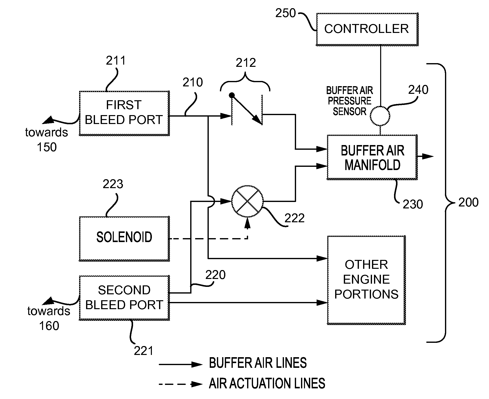
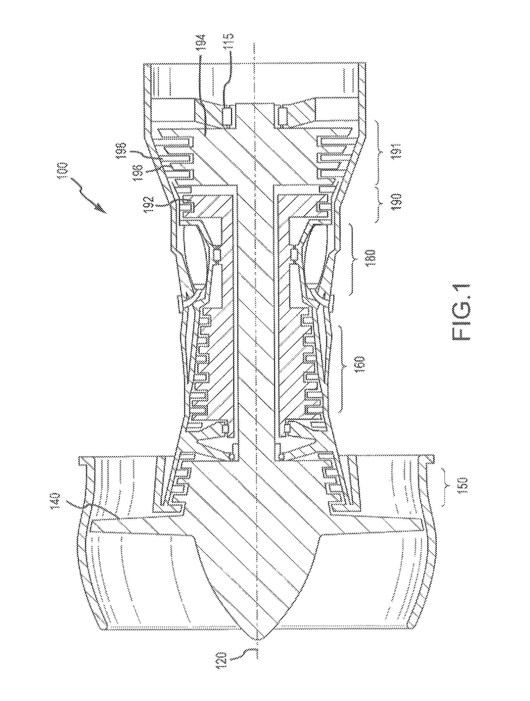
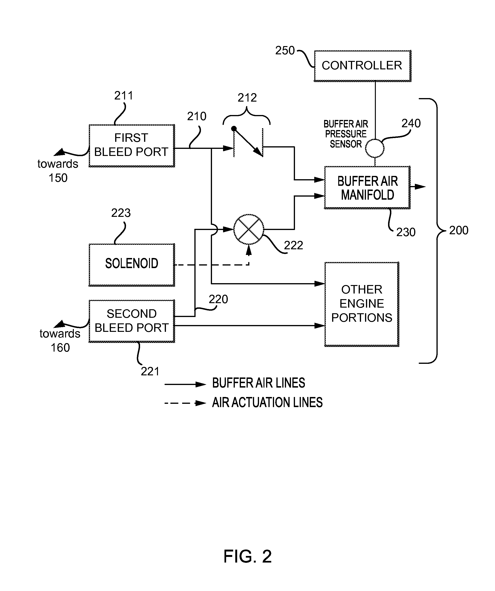
FIELD OF THE DISCLOSURE[0001]The present disclosure relates to fault detection systems and methods, and more particularly, to detecting valve failures in a buffer air system.BACKGROUND OF THE DISCLOSURE[0002]Gas turbine engines typically include at least a compressor section, a combustor section, and a turbine section. Such engines may also include a buffer air system. In a buffer air system, multiple bleed ports are regulated by valves and communicate air from the compressor sections to a manifold, from which buffer supply air may be communicated to other portions of the engine or released externally from the engine.[0003]Buffer air systems and mechanical systems in general may fail. The failure of buffer air system valves may impede the proper functioning of the gas turbine engine, as well as systems the engine may power.SUMMARY OF THE DISCLOSURE[0004]In various embodiments, the present disclosure provides methods, systems, and computer-readable media for the detection of valve fa...

Claims


Application Information

Patent Timeline
Patent Type & Authority Patents(United States)
IPC IPC(8): F02C9/18G01M3/28F15B19/00F16K37/00F15B20/00
CPCF02C9/18F15B19/005F15B20/008F16K37/0091G01M3/2876
Inventor CLAUSON, JESSE W.LEGG, ERIC E.
Owner RTX CORP
Learn More