
Lighting control switch apparatus and system

a technology of control switch and switch body, which is applied in the direction of lighting apparatus, light source, electric lighting source, etc., can solve the problems of reducing or preventing the majority of end-users from achieving an acceptable payback scenario, affecting the overall economic benefits of the system, and adding wiring installations

Inactive Publication Date: 2017-01-10
YWIRE TECH
View PDF74 Cites 30 Cited by
  • Summary
  • Abstract
  • Description
  • Claims
  • Application Information

AI Technical Summary

Benefits of technology

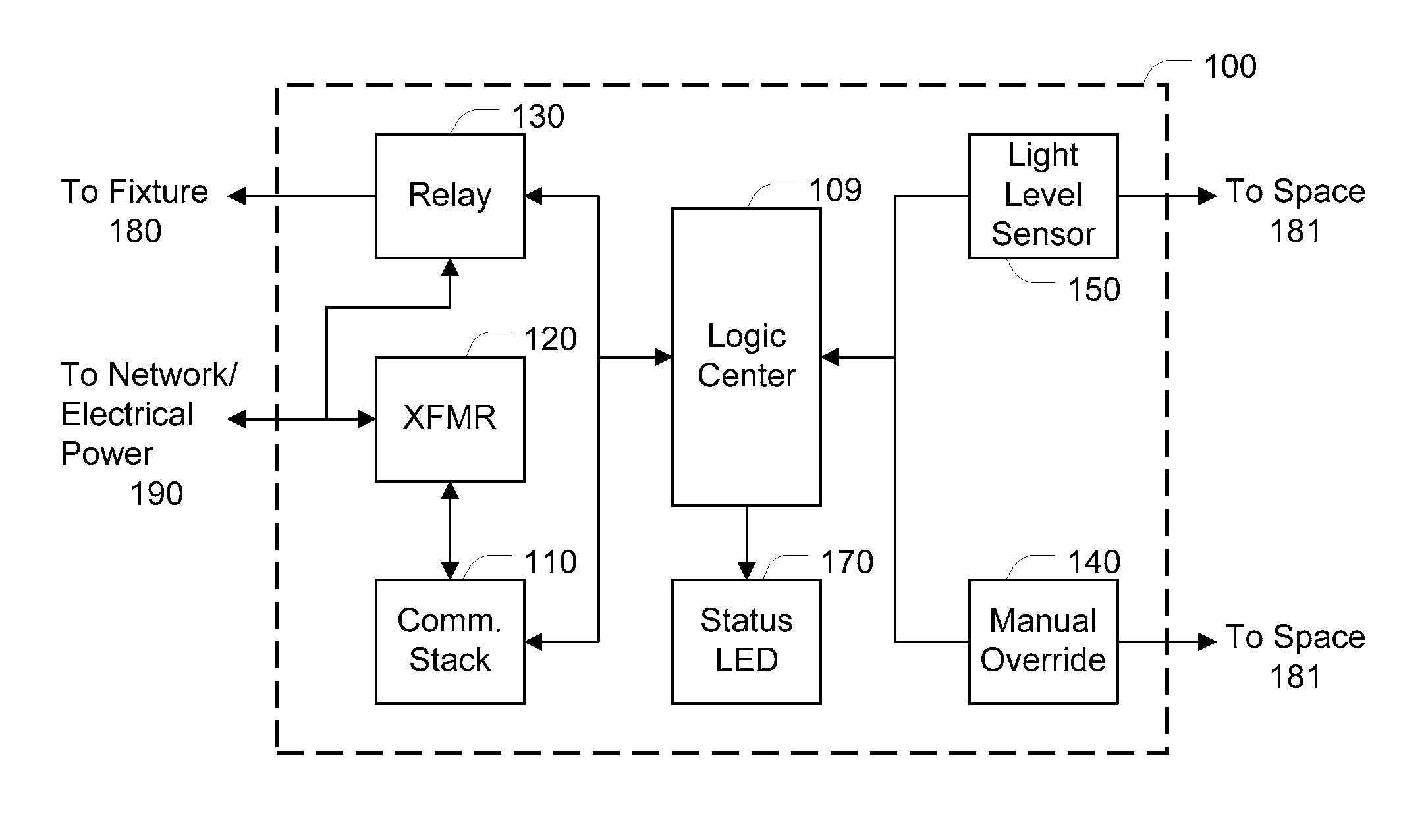
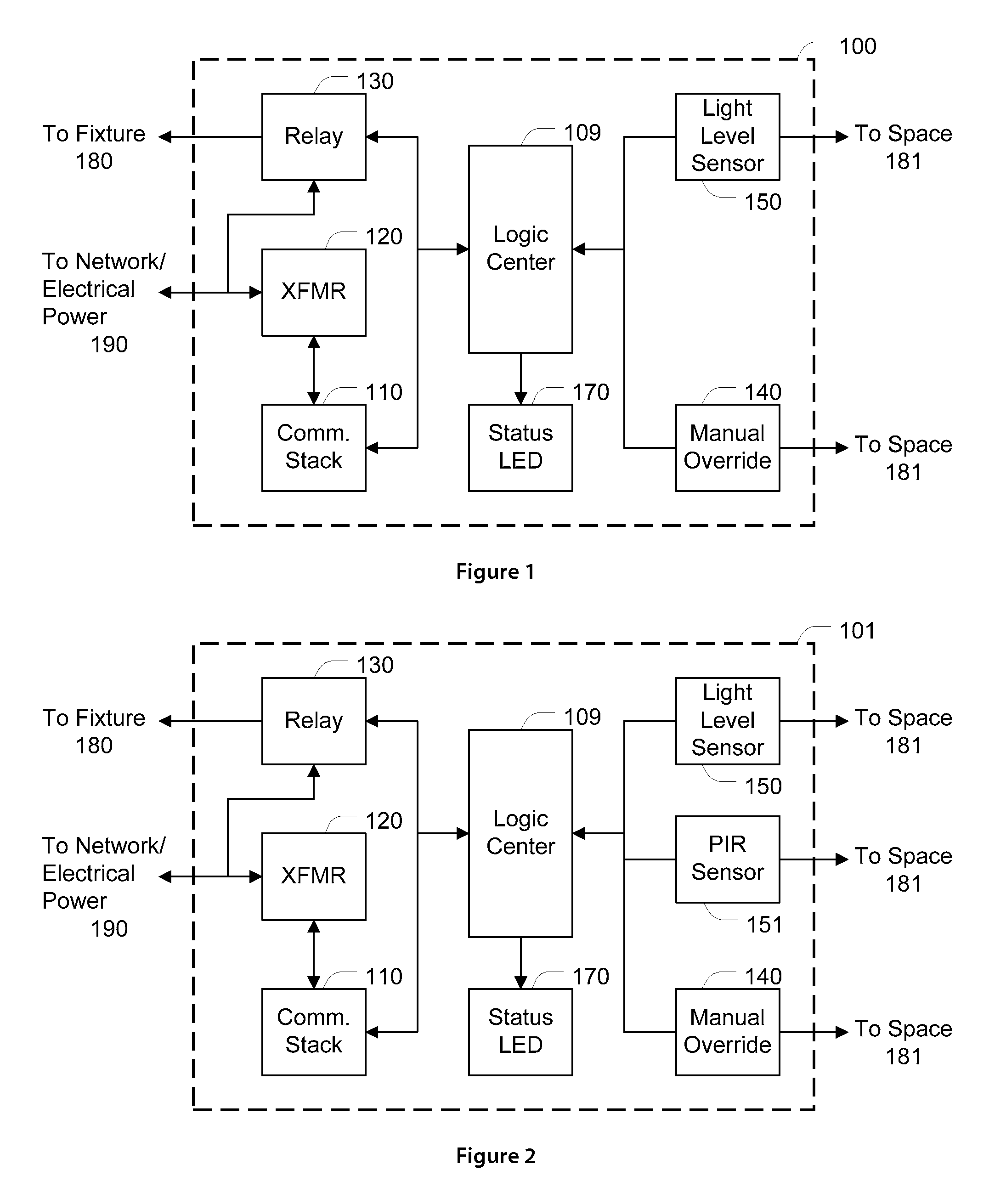
The present invention is an apparatus that combines the functions of a light switch and powerline communication technology, like BPL. It provides a reliable and fully addressable communication network for comprehensive lighting control without the need for circuit relocation or ballast replacement. This can save over 80% in installation costs compared to existing high-end lighting control systems. Additionally, it allows for integration with the emerging SmartGrid.

Problems solved by technology

However, current lighting control solutions require additional wiring installations in order to relocate electric switching to a central panel.
The alteration of an electrical infrastructure creates an installed cost burden, and reduces or prevents an acceptable payback scenario for the majority of end-users.
Such high-end systems require a substantial financial investment, and also a commitment to the inconveniences of the retrofit installation process.

Method used


Image

  • Lighting control switch apparatus and system
  • Lighting control switch apparatus and system
  • Lighting control switch apparatus and system

Examples


Embodiment Construction

[0024]The following description is presented to enable any person skilled in the art to make and use the invention, and is provided in the context of particular applications of the invention. Various modifications to the disclosed embodiments will be readily apparent to those skilled in the art, and the general principles defined herein may be applied to other embodiments and applications without departing from the scope of the present invention. Reference to various embodiments and examples does not limit the scope of the invention, which is limited only by the scope of the claims attached hereto. Additionally, any examples set forth in this specification are not intended to be limiting and merely set forth some of the many possible embodiments for the claimed invention.

[0025]The program environment in which a present embodiment of the invention is executed illustratively incorporates a general-purpose computer or a special purpose device such as a hand-held computer. Details of su...


PUM


Abstract

An improved hardware light switch and a system comprising at least one of the light switches and control / monitoring means is disclosed. The improved light switch and system provide a more flexible, convenient and economical means to reduce energy consumption both at the switch and remotely. In a first configuration, the improved light switch comprises an electronic switch, a broadband powerline communication (PLC) transceiver that includes processing ability, a unique MAC address and a TCP / IP stack.

Description

COPYRIGHT NOTICE[0001]A portion of the disclosure of this patent document contains material which is subject to copyright protection. The copyright owner has no objection to the facsimile reproduction by anyone of the patent document or the patent disclosure, as it appears in the Patent and Trademark Office patent file or records, but otherwise reserves all copyright rights whatsoever.BACKGROUND OF THE INVENTION[0002]Conservation has been the topic of national energy campaigns, and one approach to saving energy is to turn off lighting when not in use. This can be accomplished most effectively through automated lighting control that does not rely on human intervention. Net worked lighting control has existed in some form for more than 20 years. However, current lighting control solutions require additional wiring installations in order to relocate electric switching to a central panel. The alteration of an electrical infrastructure creates an installed cost burden, and reduces or pre...

Claims


Application Information

Patent Timeline
Patent Type & Authority Patents(United States)
IPC IPC(8): H05B37/02
CPCH05B37/0227H05B37/0218H05B37/0254H05B37/0263Y02B20/46H05B47/18H05B47/11Y02B20/40H05B47/115H05B47/13H05B47/1965H05B47/187H05B47/185H05B47/105
Inventor GILTACA, ROD M.TABBA, OMARSMITH, R. KYLECASSANI, PABLO
Owner YWIRE TECH
Learn More