
High frequency coil unit and magnetic resonance imaging apparatus

a high-frequency coil unit and magnetic resonance imaging technology, applied in the field of magnetic resonance imaging (mri) technique, can solve the problems of unfavorable contrast and/or artifact generation, and achieve the effect of reducing the variation of performance, low cost, and easy obtaining of elliptical bird cage coils

Active Publication Date: 2017-01-10
FUJIFILM HEALTHCARE CORP
View PDF15 Cites 8 Cited by
  • Summary
  • Abstract
  • Description
  • Claims
  • Application Information

AI Technical Summary

Benefits of technology

This approach results in a cost-effective and efficient manufacturing process with reduced variations in coil performance, simplifying the production of elliptical birdcage coils while maintaining homogeneous sensitivity distribution and resonant mode at the magnetic resonance frequency.

Problems solved by technology

This is because if high inhomogeneity exists in the distribution of the RF magnetic field, a difference may occur in the excited state of the nuclear spins, depending on portions in the test subject, and unevenness of contrast and / or an artifact may be generated in the image being obtained.

Method used


Image

  • High frequency coil unit and magnetic resonance imaging apparatus
  • High frequency coil unit and magnetic resonance imaging apparatus
  • High frequency coil unit and magnetic resonance imaging apparatus

Examples


first embodiment

[0048]Hereinafter, the first embodiment to which the present invention is applied will be explained. In all the following figures for explaining the embodiments of the present invention, the constituents having the same function are labeled the same, and tedious explanations will not be made.

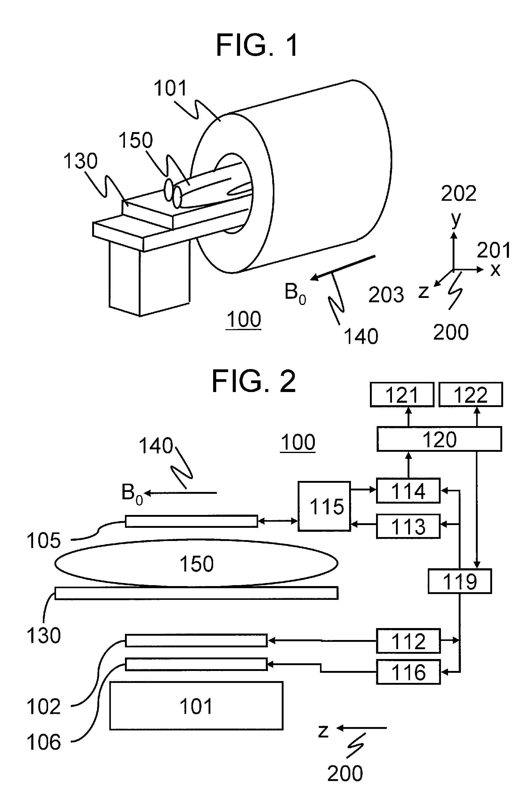
[0049]Firstly, an overall configuration of the MRI apparatus according to the present embodiment will be explained. FIG. 1 illustrates an overview of the MRI apparatus according to the present embodiment. FIG. 1 illustrates the MRI apparatus 100 provided with a magnet 101 intended for a horizontal magnetic field system. The test subject 150 is inserted into the imaging space within a bore of the magnet 101 in the state of being laid on a table 130, and subjected to imaging. It is to be noted that the present embodiment employs the coordinate system 200 in which the static magnetic field 140 (B0) generated by the magnet 101 of the horizontal magnetic field system is in the direction of z-axis 203...

second embodiment

[0203]Next, a second embodiment to which the present invention is applied will be explained. The MRI apparatus according to the present embodiment is basically the same as that of the first embodiment. In the first embodiment, the transceive RF coil is used for transmitting an RF magnetic field and receiving a magnetic resonance signal. On the other hand, in the present embodiment, there are provided separately, a transmit RF coil for transmitting the RF magnetic field and a receive RF coil for receiving the magnetic resonance signal. Hereinafter, an explanation will be made as to the present embodiment, focusing on the configuration being different from the first embodiment. It is to be noted that the present embodiment also uses the coordinate system 200 in which the orientation of the static magnetic field 140 generated by the magnet 101 of the horizontal magnetic field system is assumed as the z-axis direction.

[0204]FIG. 13 illustrates a block diagram showing a schematic configu...


PUM


Abstract

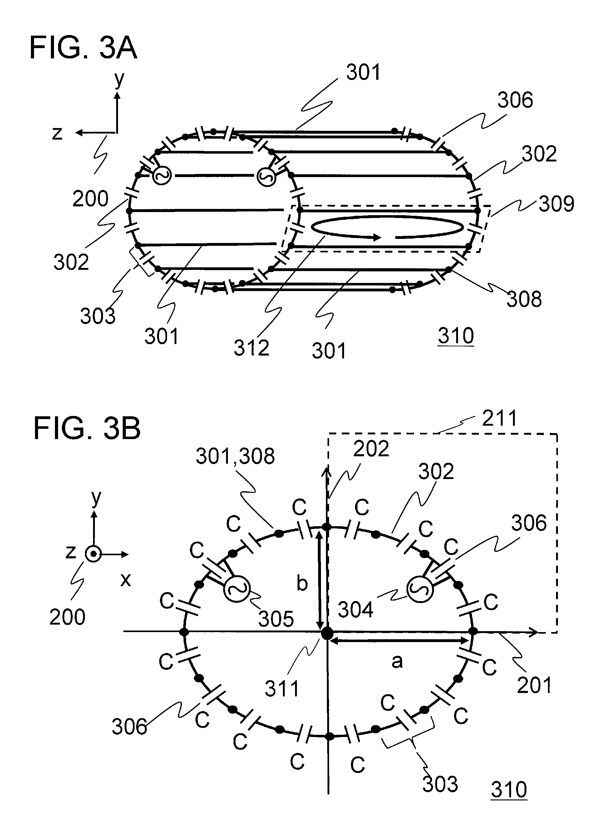
The present invention is directed to an elliptical birdcage coil which reduces time and effort upon manufacturing and production cost, with less variations in performance. There is provided a high frequency coil unit made up of the elliptical birdcage coil having plural capacitors arranged at least on either of the ring conductors and the rung conductors, the capacitance of the plural capacitors being uniform with respect to each conductor type on which the capacitors are placed. In this elliptical birdcage coil, a value of inductance and arrangement of the ring conductors and the rung conductors are determined in such a manner that the capacitance of the capacitors becomes identical with respect to each conductor type on which the capacitors are arranged.

Description

TECHNICAL FIELD[0001]The present invention relates to a magnetic resonance imaging (MRI) technique, and more particularly, it relates to a technique for carrying out irradiation of electromagnetic waves and detection of magnetic resonance signals.BACKGROUND ART[0002]An MRI (magnetic resonance imaging) apparatus is a medical diagnostic imaging apparatus that produces magnetic resonance in a nuclear spin within an arbitrary cross section passing transversely across a test subject, and obtains a tomographic image in the cross section based on the magnetic resonance signals being generated. When a test subject placed in a static magnetic field is irradiated with an RF magnetic field from a high frequency coil (RF coil), together with application of a gradient magnetic field, a nuclear spin within the test subject, a nuclear spin of hydrogen atom, for instance, is excited. When the nuclear spin being thus excited restores to an equilibrium state, a magnetic field of circularly polarized ...

Claims


Application Information

Patent Timeline
Patent Type & Authority Patents(United States)
IPC IPC(8): G01R33/34A61B5/055
CPCG01R33/34A61B5/055G01R33/34076
Inventor SOUTOME, YOSHIHISABITO, YOSHITAKAHABARA, HIDETA
Owner FUJIFILM HEALTHCARE CORP
Learn More