
Clutch

a clutch and friction technology, applied in the field of friction clutches, can solve the problems of difficult to precisely control the torque transmissible by the clutch, the movability of the frictional partners in the tooth arrangement may be made more difficult, etc., and achieve the effect of cost and operation benefits

Active Publication Date: 2017-01-10
SCHAEFFLER TECH AG & CO KG
View PDF13 Cites 0 Cited by
  • Summary
  • Abstract
  • Description
  • Claims
  • Application Information

AI Technical Summary

Benefits of technology

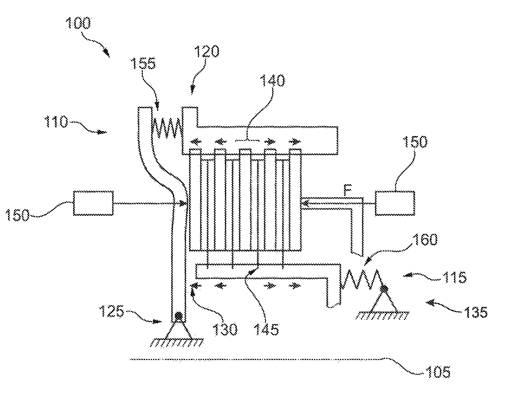
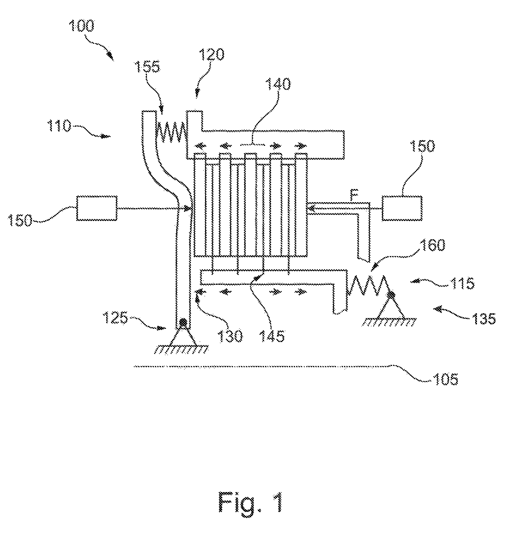
[0008]In contrast to a known solution in which the structure of frictional partners is compressed axially against the input side or against the output side, the axial forces of the described compression device may be distributed more uniformly between the frictional partners. This makes it possible to reduce a loss of axial force for a frictional partner as the distance from the side actuated by the compression device increases. Together with the loss of axial force, it is also possible to reduce a hysteresis behavior which may be observed between the axial force exerted by the compression device and the torque that is transmissible by means of the clutch. The torque transmissible by means of the clutch can be better controlled by means of the axial force. In a drivetrain, a transmitted torque can be better controlled by means of the clutch. If the drivetrain serves to propel a motor vehicle, then acceleration or deceleration of the motor vehicle can be better controlled by means of the drivetrain.
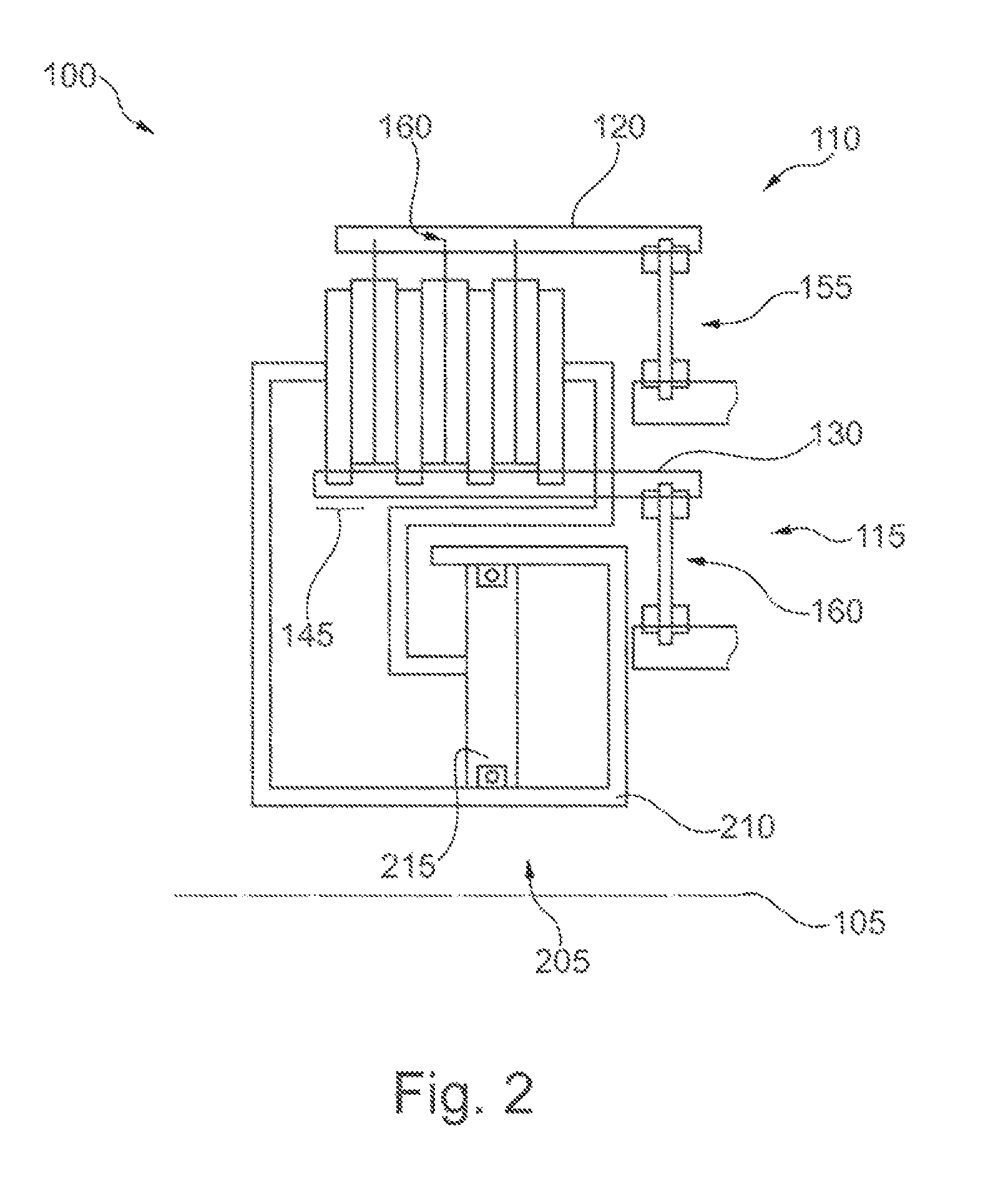
[0009]In an example embodiment, the sides, i.e. the input side and the output side, are decoupled in such a way that the compressed frictional partners are jointly movable axially in relation to the input side and the output side. This enables an especially uniform distribution of axial forces between the individual frictional partners. In theory, it is possible to halve the loss of axial force and of the hysteresis behavior.
[0010]In an example embodiment, the decoupling of one of the sides occurs by means of an axially elastic element, which is set up to transmit the torque that is transmissible by means of the clutch. This makes it possible to combine a simple and efficient axial decoupling with an equally simple and efficient radial or axial transmission of torque.
[0011]In an example embodiment, the axially elastic element comprises a diaphragm spring. The diaphragm spring can represent an economical and stable embodiment of the axially elastic element. The transmission behavior of the diaphragm spring for torque can be especially good here.
[0014]In an example embodiment, the compression device includes a hydraulic actuator, which operates axially on the frictional partners. The axial movability of the structure of frictional partners can be designed to integrate with a hydraulic compression device. This can provide operating and cost benefits.
[0015]In an example embodiment, the compression device also includes another hydraulic actuation system, which acts on the structure of frictional partners antiparallel to the first hydraulic actuation system. In this way, an axial position of the arrangement can adjust itself especially well during the axial actuation, so that the distribution of axial forces onto the individual frictional partners can be accomplished especially uniformly.

Problems solved by technology

This rotation exerts a force operating in a circumferential direction, which puts a strain on the tooth arrangement of the frictional partners, so that the movability of the frictional partners in the tooth arrangement may be made more difficult.
This loss of axial force may lead to torque hysteresis, which may make it difficult to precisely control the torque transmissible by means of the clutch.

Method used


Image

  • Clutch
  • Clutch
  • Clutch

Examples


Embodiment Construction

[0021]At the outset, it should be appreciated that like reference characters on different drawing views identify identical, or functionally similar, structural elements of the invention. While the present invention is described with respect to what is presently considered to be the preferred aspects, it is to be understood that the invention as claimed is not limited to the disclosed aspect. The present invention is intended to include various modifications and equivalent arrangements within the spirit and scope of the appended claims.

[0022]Furthermore, it is understood that this invention is not limited to the particular methodology, materials and modifications described and as such may, of course, vary. It is also understood that the terminology used herein is for the purpose of describing particular aspects only, and is not intended to limit the scope of the present invention, which is limited only by the appended claims.

[0023]Unless defined otherwise, all technical and scientifi...


PUM


Abstract

A clutch comprises an input side and an output side, which are disposed rotatably. First frictional partners are non-rotatably connected with the input side and axially movable and second frictional partners are non-rotatably connected with the output side and axially movable. Furthermore, a compression device is provided to compress the frictional partners axially, in order to provide a torsional connection between the input side and the output side. Both sides are decoupled axially from the respective frictional partners with which they are engaged.

Description

CROSS-REFERENCE TO RELATED APPLICATIONS[0001]The present application is the U.S. national stage application pursuant to 35 U.S.C. §371 of International Application No. PCT / DE2013 / 200331, filed on Nov. 29, 2013, which application claims priority from German Patent Application No. DE 10 2012 223 386.5, filed on Dec. 17, 2012, which applications are incorporated herein by reference in their entireties.FIELD OF THE INVENTION[0002]The present invention relates generally to a clutch, and, more specifically, to a friction clutch for transmitting torque in a drivetrain of a motor vehicle.BACKGROUND OF THE INVENTION[0003]A clutch, in particular a multiple plate wet clutch, generally includes an input component and an output component, which are supported coaxially to each other so that they can rotate with respect to each other. A first set of frictional elements are non-rotatably connected to the input component and are capable of being axially displaced. Similarly, a second set of friction...

Claims


Application Information

Patent Timeline
Patent Type & Authority Patents(United States)
IPC IPC(8): F16D13/52F16D13/68F16D25/0638F16D27/115
CPCF16D13/686F16D13/52F16D13/683F16D25/0638F16D27/115
Inventor GOETZ, ANDREAS
Owner SCHAEFFLER TECH AG & CO KG
Learn More