
Connector assembly

a technology of connecting parts and connectors, applied in the direction of coupling device details, coupling device connections, soldered/welded connections, etc., can solve the problem of not being able to increase the diameter of the cavity inser

Active Publication Date: 2017-01-03
TYCO ELECTRONICS LOGISTICS AG (CH)
View PDF15 Cites 19 Cited by
  • Summary
  • Abstract
  • Description
  • Claims
  • Application Information

AI Technical Summary

Benefits of technology

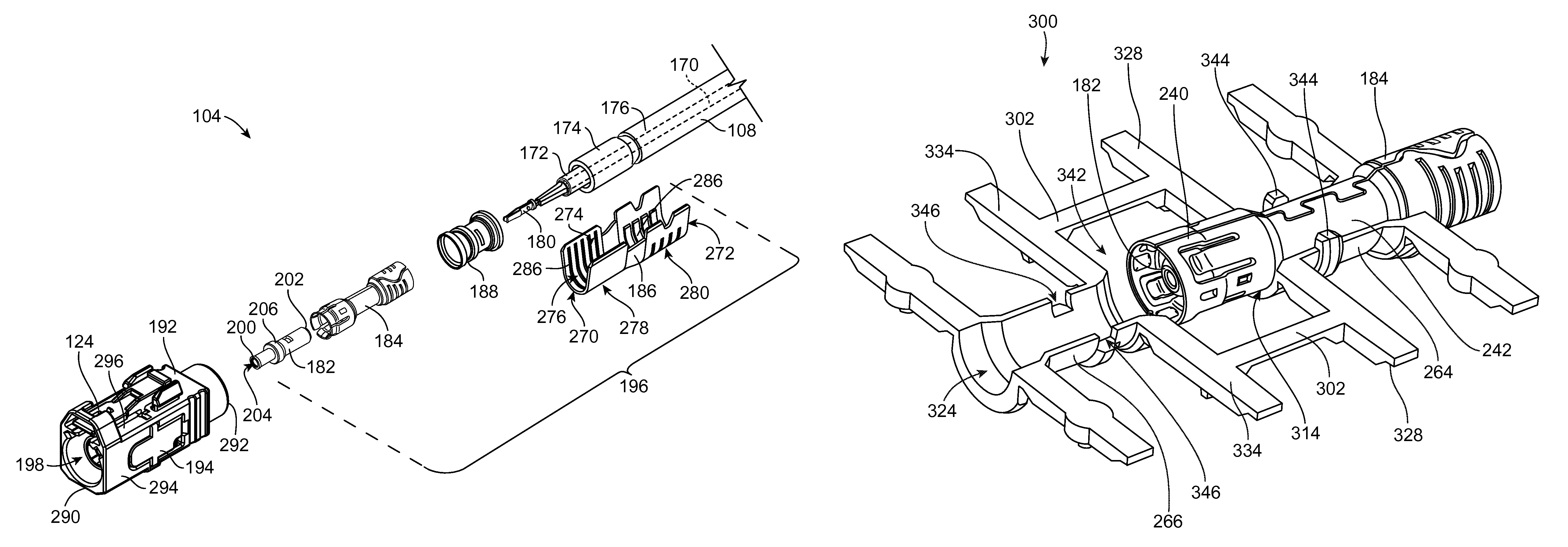
This patent text describes a connector assembly with a center contact, dielectric, outer contact, and cavity insert. The connector assembly is designed to be connected to a cable with a braid. The mating segment of the outer contact is connected to the center conductor of the cable, while the termination segment is connected to the braid. The cavity insert is made up of a receiving shell and closing shell that are joined together at an interface. The technical effect of this design is the improved reliability and durability of the connector assembly, which can withstand high amounts of force and is resistant to corrosion.

Problems solved by technology

However, it may not be feasible to increase the diameter of the cavity insert to allow the cavity insert to fit over the cable end and / or mating end due to space restrictions within the outer housings.

Method used


Image

  • Connector assembly
  • Connector assembly
  • Connector assembly

Examples


Embodiment Construction

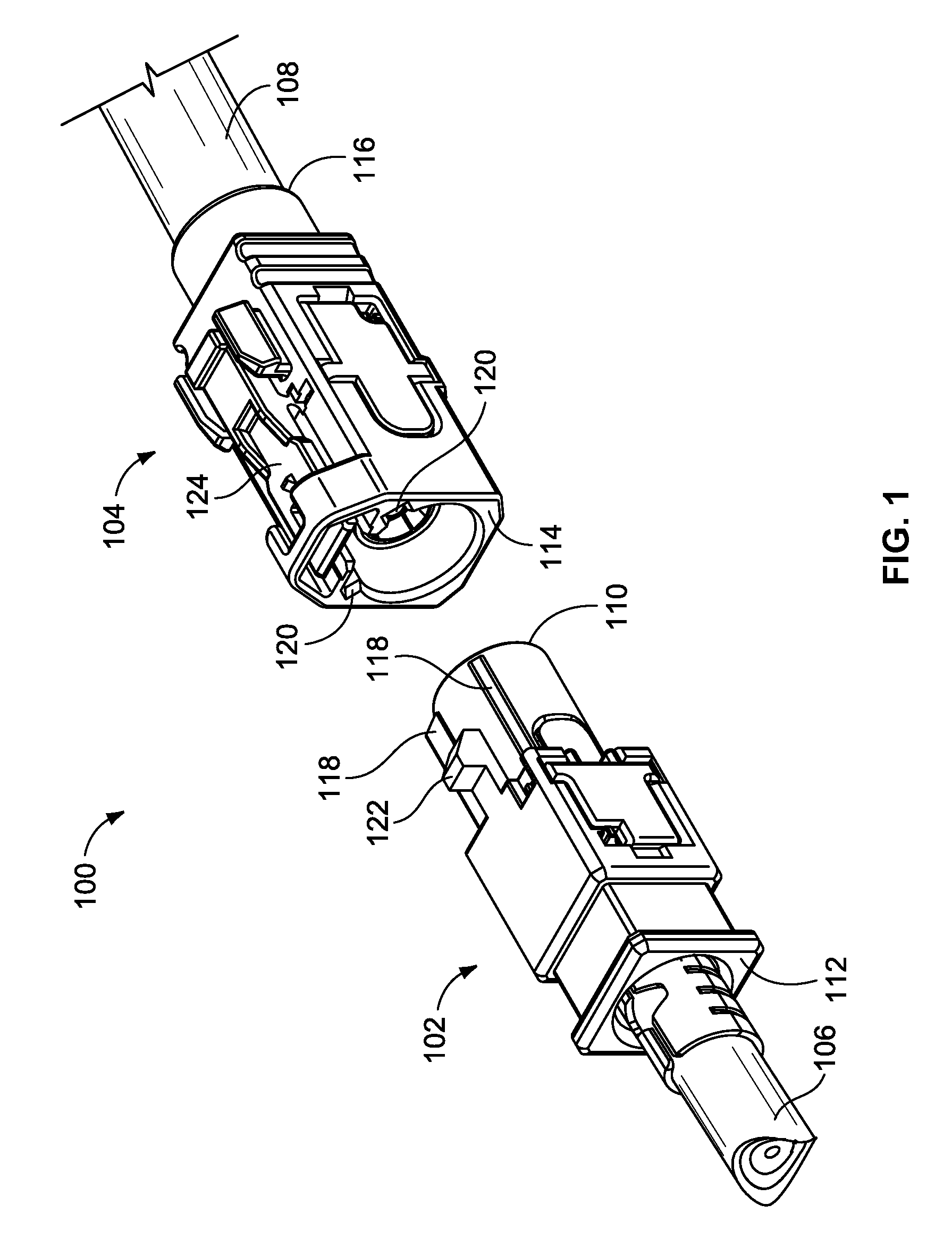
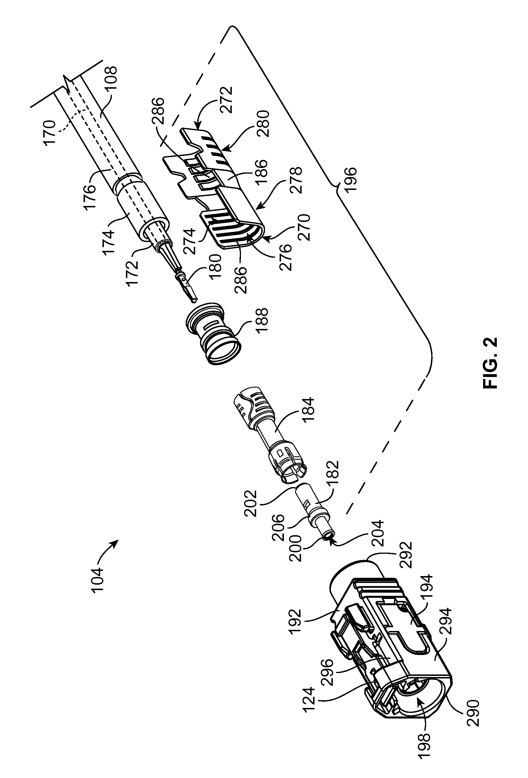
[0018]FIG. 1 illustrates a connector system 100 formed in accordance with an exemplary embodiment. The connector system 100 includes a first connector assembly 102 and a second connector assembly 104. The first connector assembly 102 and the second connector assembly 104 are configured to be connected together to transmit electrical signals therebetween. For example, a center contact and an outer contact of the first connector assembly 102 may engage respective center and outer contacts of the second connector assembly 104 to provide a conductive signal path across the connector assemblies 102, 104. Optionally, the first connector assembly 102 may constitute a jack assembly, such that the center contact has a pin at a mating end that engages the center contact of the second connector assembly 104. Conversely, the second connector assembly 104 may be a plug assembly, such that the center contact forms a socket at a mating end that is configured to receive the pin of the first connect...


PUM


Abstract

A connector assembly includes a center contact configured to be terminated to a center conductor of a cable. A dielectric holds the center contact. An outer contact surrounds the dielectric and the center contact. The outer contact has a mating segment extending from a mating end, a terminating segment extending from a cable end, and a middle segment between the mating and terminating segments. The terminating segment is configured to be terminated to a braid of the cable. The middle segment has a diameter that is less than the respective diameters of the mating and terminating segments. A cavity insert surrounds the middle segment of the outer contact. The cavity insert includes a receiving shell and a closing shell that are joined together at an interface.

Description

BACKGROUND OF THE INVENTION[0001]The subject matter herein relates generally to connector assemblies.[0002]Radio frequency (RF) connector assemblies have been used for numerous applications including military applications and automotive applications, such as global positioning systems (GPS), antennas, radios, mobile phones, multimedia devices, and the like. The connector assemblies are typically coaxial cable connectors that are provided at the end of coaxial cables.[0003]In order to standardize various types of connector assemblies, particularly the interfaces for such connector assemblies, certain industry standards have been established. One of these standards is referred to as FAKRA, which is an abbreviation for the German term Fachnormenausschuss Kraftfahrzeugindustrie. FAKRA is the Automotive Standards Committee in the German Institute for Standardization, representing international standardization interests in the automotive field. The FAKRA standard provides a system, based ...

Claims


Application Information

Patent Timeline
Patent Type & Authority Patents(United States)
IPC IPC(8): H01R9/05H01R13/52H01R43/02H01R13/434H01R24/40H01R103/00
CPCH01R9/0518H01R13/434H01R24/40H01R43/0207H01R13/521H01R2103/00H01R13/506
Inventor HALL, JOHN WESLEYDUESTERHOEFT, SCOTT STEPHEN
Owner TYCO ELECTRONICS LOGISTICS AG (CH)
Learn More