Systems and methods to avoid instability conditions in a source plasma chamber

a plasma chamber and instability technology, applied in the field of laser systems, can solve the problems of laser beam slowly drifting into a region of such oscillation, undesirable variations in wafer euv light exposure,

Active Publication Date: 2017-01-03
ASML NETHERLANDS BV
View PDF3 Cites 4 Cited by
  • Summary
  • Abstract
  • Description
  • Claims
  • Application Information

AI Technical Summary

Benefits of technology

[0010]In another embodiment, a laser-produced plasma (LPP) extreme ultraviolet (EUV) system comprises: a laser source configured to fire laser pulses at a primary focus point within an LPP EUV source plasma chamber of the LPP EUV system; an energy detector configured to detect an amount of EUV energy generated when one or more of the laser pulses hits a target material; and, a system controller configured to: detect that the amount of generated EUV energy is approaching an unstable sinusoidal condition; and, direct a focusing optic of the LPP EUV system move the laser beam along a Y-axis of the LPP EUV source plasma chamber.
[0011]In a further embodiment, is a non-transitory compu

Problems solved by technology

In operation, the resulting EUV energy produced by the LPP EUV system 100 can experience oscillations which cause undesirable variations in wafer EUV light exposure.
Further, a drifting of the focus

Method used


Image

  • Systems and methods to avoid instability conditions in a source plasma chamber
  • Systems and methods to avoid instability conditions in a source plasma chamber
  • Systems and methods to avoid instability conditions in a source plasma chamber

Examples


Embodiment Construction

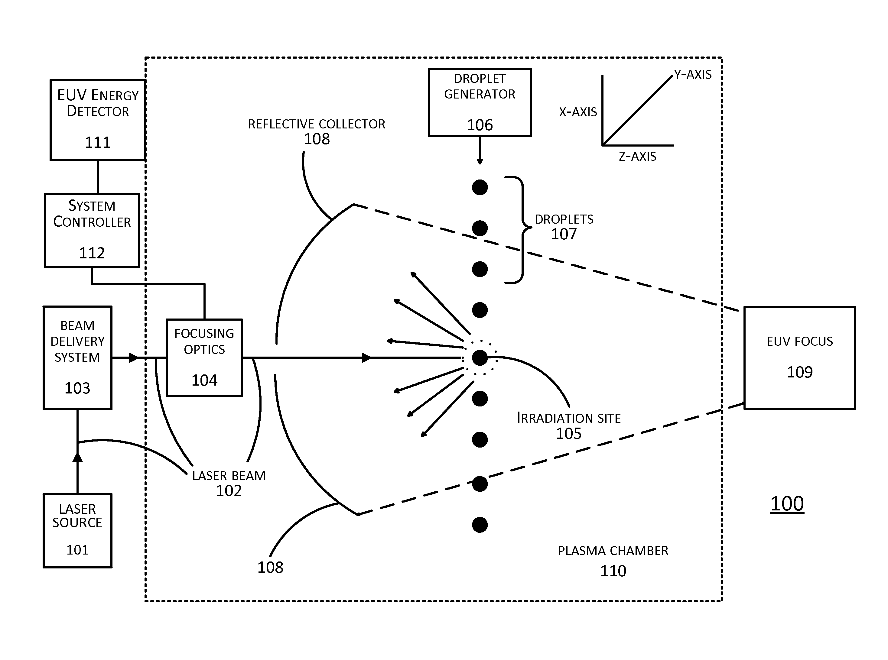
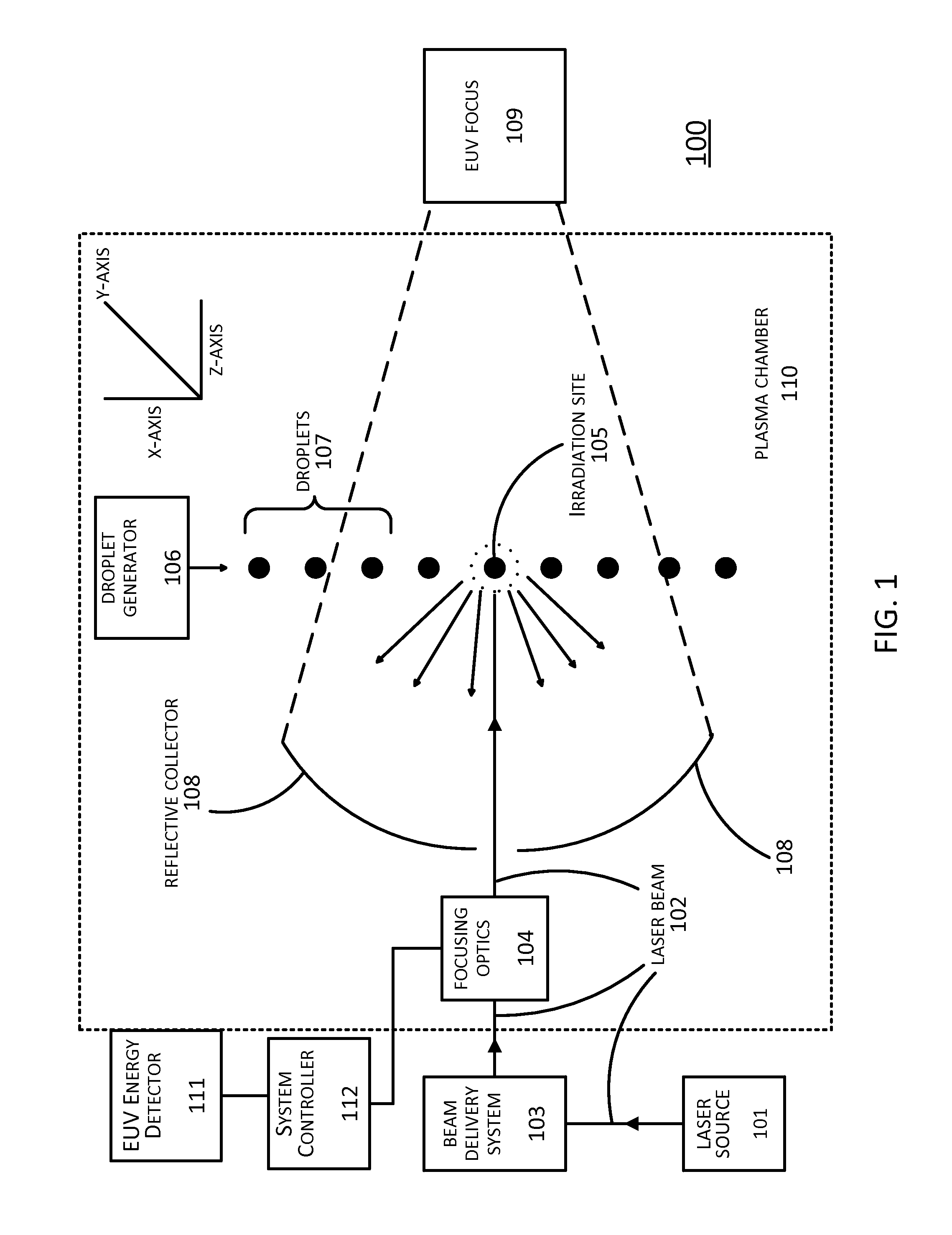
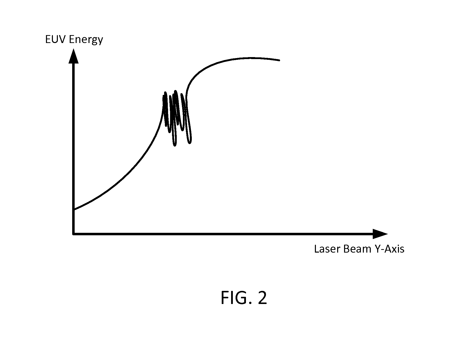
[0024]In LPP EUV systems, the amount of EUV energy generated is maximized when a droplet arrives at a primary focus point at the same time as a pulse of a laser beam. Conversely, when the droplet and laser beam do not both arrive at the primary focus point at the same time, the droplet is not completely irradiated by the laser beam. When that occurs, the laser beam, instead of squarely hitting the droplet, may only hit a portion of the droplet or miss the droplet entirely. This results in a lower-than-expected level of EUV energy being generated from the droplet. Repeated instances of this can appear as oscillations or instabilities in the resulting EUV energy level. Similarly, other factors such as laser beam focusing drift caused drifting of the focusing optics of the LPP EUV system can likewise cause instabilities in the level of generated EUV energy.

[0025]Prior approaches to dealing with these problems have been directed towards stabilizing the oscillations, with mixed results. ...


PUM


Abstract

In LPP EUV systems, sinusoidal oscillations or instabilities can occur in the generated EUV energy. This is avoided by detecting when the LPP EUV system is approaching such instability and adjusting the LPP EUV system by moving the laser beam of the LPP EUV system. Detection is done by determining when the generated EUV energy is at or above a primary threshold. Adjusting the LPP EUV system by moving the laser beam is done for a fixed period of time, until a subsequently generated EUV energy is below the primary threshold, until a subsequently generated EUV energy is below the primary threshold for a fixed period of time, or until a subsequently generated EUV energy is at or below a secondary threshold below the primary threshold.

Description

BACKGROUND[0001]Field[0002]The present application relates generally to laser systems and, more specifically, to avoiding oscillation conditions in extreme ultraviolet light energy generated within a source plasma chamber.[0003]Related Art[0004]The semiconductor industry continues to develop lithographic technologies which are able to print ever-smaller integrated circuit dimensions. Extreme ultraviolet (“EUV”) light (also sometimes referred to as soft x-rays) is generally defined to be electromagnetic radiation having wavelengths of approximately between 10 and 100 nm. EUV lithography is generally considered to include EUV light at wavelengths in the range of 10-14 nm, and is used to produce extremely small features (e.g., sub-32 nm features) in substrates such as silicon wafers. These systems must be highly reliable and provide cost-effective throughput and reasonable process latitude.[0005]Methods to generate EUV light include, but are not necessarily limited to, converting a mat...

Claims


Application Information

Patent Timeline
IPC IPC(8): H05G2/00G21K1/08
CPCG21K1/08H05G2/003H05G2/00H05G2/005H05G2/008H05G2/001
Inventor RIGGS, DANIEL JASON
Owner ASML NETHERLANDS BV
Why Eureka
Try Eureka