
System and method for stably infusing gas into liquid, and methods of using the gas infused liquid

Active Publication Date: 2016-12-27
GAPS TECH LLC +1
View PDF23 Cites 20 Cited by
  • Summary
  • Abstract
  • Description
  • Claims
  • Application Information

AI Technical Summary

Benefits of technology

This patent describes a system for injecting liquids into a vessel, such as a tank, with a pressure nozzle. The nozzle has a reduced wall thickness and is designed to prevent cavitation of the liquid as it exits the nozzle. This prevents some of the liquid from coming out of the nozzle and potentially contaminating the surrounding environment, which can reduce the efficiency of the system. Additionally, if there is solid matter in the liquid, the nozzle can self-clean by increasing the pressure to flush out the solid matter. This prevents clogging of the nozzle and allows for continued use. The system also includes minor flow passages that help break up the liquid into fine droplets and prevent water hammer. Overall, this system provides improved efficiency and prevents contamination during liquid injection.

Problems solved by technology

This leads to generation of smaller and more stable nanobubbles in the gas-infused carrier fluid, and most significantly—can cause the gas to become completely or substantially completely dissolved in the liquid, even at high gas concentration levels.

Method used


Image

  • System and method for stably infusing gas into liquid, and methods of using the gas infused liquid
  • System and method for stably infusing gas into liquid, and methods of using the gas infused liquid
  • System and method for stably infusing gas into liquid, and methods of using the gas infused liquid

Examples


Embodiment Construction

System for Infusing Gas into Liquid

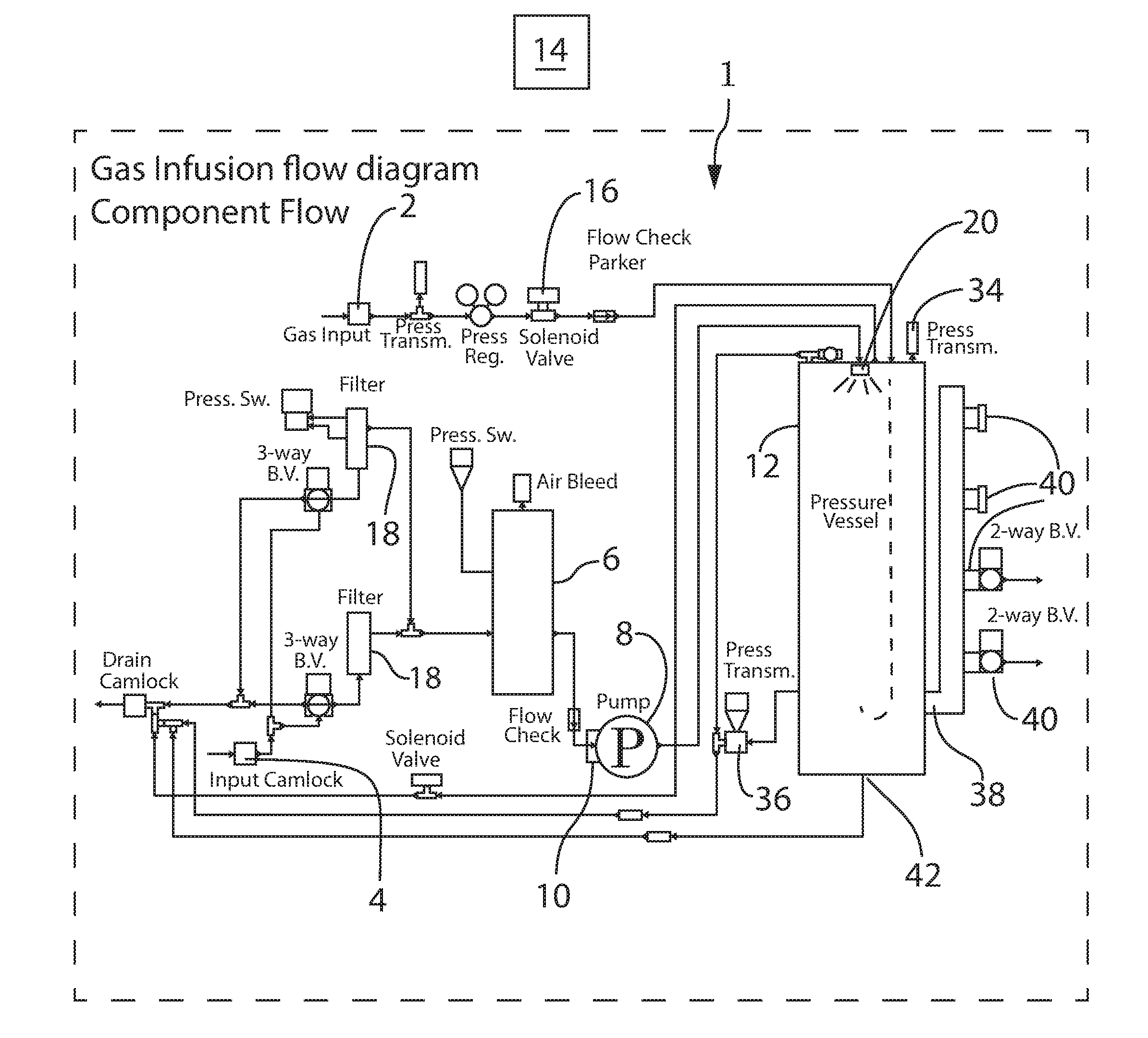
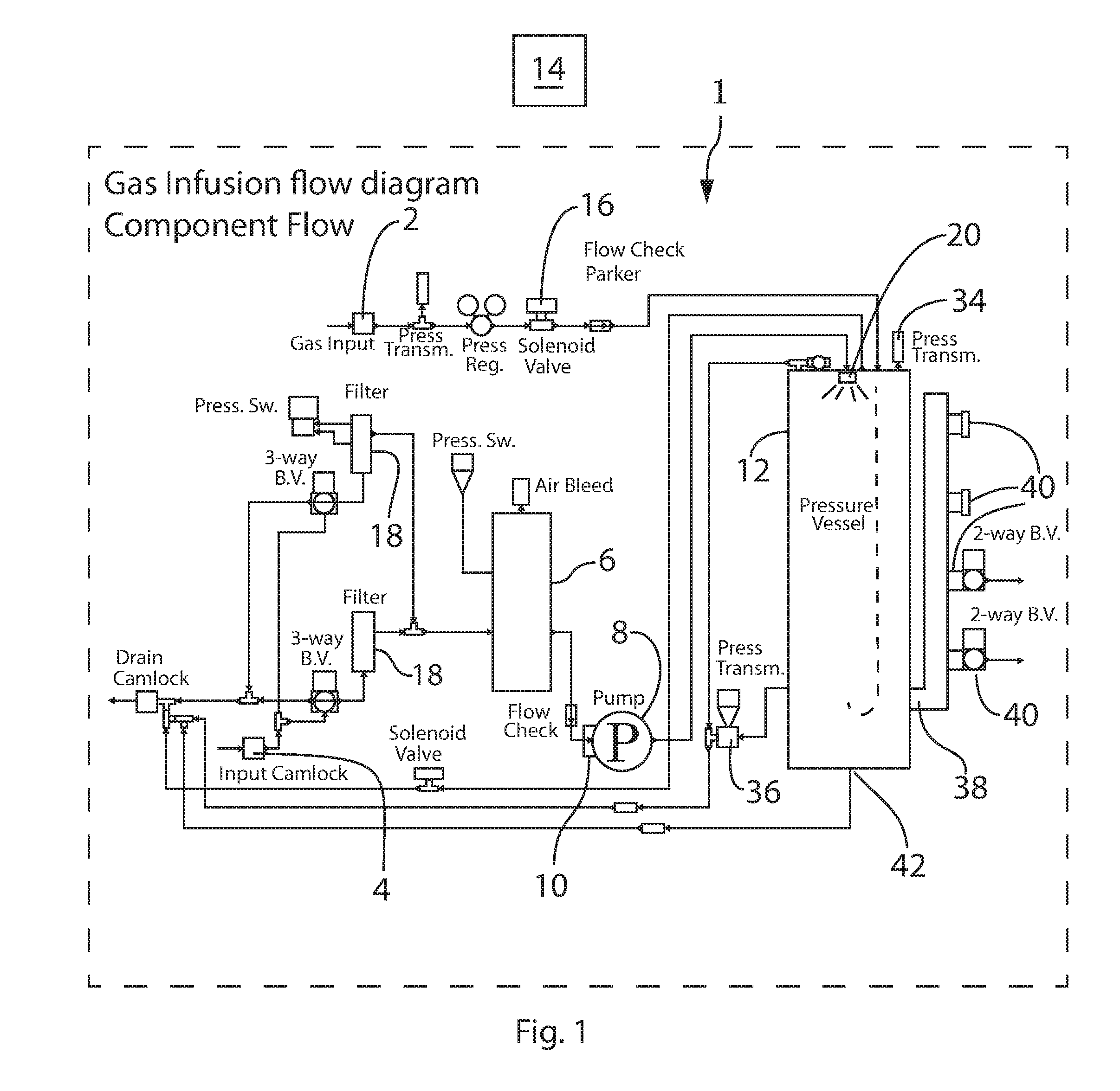
[0026]With reference to FIG. 1 there is shown a schematic diagram of a system 1 for generating a gas-infused liquid under hyperbaric conditions according to an exemplary embodiment of the present invention. The system 1 generally includes a pressurized gas source 2, a source of water, an aqueous liquid, or other liquid 4, a degassifier 6, a pump 8 for the liquid, a motor 10 which drives the pump, an enclosed pressure vessel 12 into which the pressurized gas and the liquid are injected for thereby generating a gas-infused fluid, and a controller 14 which controls operation of the system. Gas-infused liquid discharged from the system 1 of FIG. 1 may be directed to flow through a special flow path arrangement, an exemplary embodiment of which is shown at 100 in FIGS. 6A-6C, to thereby stabilize the infused gas in the liquid, e.g., in the form of nanobubbles, as discussed further below.

[0027]The pressurized gas source 2 may comprise any appropriate gas...


PUM

PropertyMeasurementUnit
Pressureaaaaaaaaaa
Angleaaaaaaaaaa
Angleaaaaaaaaaa

Abstract

A system for generating liquid which is stably infused with gas, including a pressurized gas source, a pressurized liquid source, an enclosed vessel into which the pressurized gas and pressurized liquid are injected such that the gas becomes infused into the liquid so as to generate a gas-infused liquid and a fluid path into which the gas-infused fluid flows after being discharged from the vessel, wherein the fluid path includes multiple radially bent sections and multiple substantially straight section fixed in a three dimensional (3D) arrangement such that the when the gas-infused carrier fluid flows through the fluid path it is pressed inwardly of the 3D arrangement from multiple different directions to effect a multi-dense, orbital or spherical compaction of elements of the gas-infused liquid thereby forming the infused gas into nanobubbles in the gas-infused liquid.

Description

BACKGROUND OF THE INVENTION1. Field of the Invention[0001]The present disclosure relates to a method and apparatus for stably infusing gas into liquid in the form of nanobubbles, and methods for using the gas infused liquid. More particularly, the present disclosure relates to such a system and method which can efficiently and stably infuse gas into liquid at higher levels and longer duration than has been previously possible, and methods of using the gas infused liquid.BACKGROUND[0002]Systems and methods are known that make use of liquids infused with a gas. For example, the present inventor has previously disclosed such a system and method in International Application PCT / US2014 / 064727, filed 10 Nov. 2014, which claims priority from U.S. Provisional Application 61 / 904,755. The disclosures of International Application PCT / US2014 / 064727 and U.S. Provisional Application 61 / 904,755 are incorporated herein by reference.[0003]The present inventor's previous disclosures identify some oth...

Claims


Application Information

Patent Timeline
IPC IPC(8): B01F3/04B01F15/02B01F15/00B01F5/00B01F5/04
CPCB01F3/0446B01F5/04B01F15/00162B01F15/00344B01F15/0254B01F15/0243B01F5/00B01F3/04056B01F23/2341B01F25/4331B01F35/2113B01F35/2211B01F23/232B01F23/2375B01F23/21321B01F25/00
Inventor ROE, CLIFFTON LEE
Owner GAPS TECH LLC
Learn More