Controlled flow roof drain
a technology of controlled flow and roof drain, which is applied in the direction of roof covering, roofs, roofs, etc., can solve the problems of water draining from flat roofs, affecting the construction efficiency of buildings, and the cost of drain lines and connector lines which run to the sewer connection constitutes a substantial portion of building manufacture costs, so as to reduce the size and thus the cost of these lines
Active Publication Date: 2016-12-13
SMITH IND INC D B A JAY R SMITH MFG CO
View PDF17 Cites 8 Cited by
- Summary
- Abstract
- Description
- Claims
- Application Information
AI Technical Summary
Benefits of technology
The patent text discusses the issue of efficient drainage from flat roofs in commercial buildings. It explains that there are two main reasons to control the rate of water removal from these roofs. Firstly, to comply with limitations set by municipal storm sewers, and secondly, to minimize the cost of drain lines and connector lines. The text then explains a common method of minimizing the rate of water removal from a flat roof by using it as a reservoir for rain or melted snow water, which allows for controlled removal at a predetermined rate. The technical effect of this method is to extend the time available for water removal from a storm while controlling the rate of excess drainage.
Problems solved by technology
The efficient drainage of water from flat roofs is an important issue in the construction of commercial buildings.
Firstly, the capacity of municipal storm sewers often dictate a mandatory limitation on the rate of water which can be removed from a roof and placed in a storm sewer for disposal.
Secondly, the cost of drain lines and connector lines which run to the sewer connection constitute a substantial portion of the cost of building manufacture.
Method used
View moreImage
Smart ImageViewing Examples

Examples
example 1
[0033]The orifice size for embodiment example “A” is calculated using Formula 1 as follows: Q for embodiment A=12 GPM at 0.25 ft head.
12=448.8×K×A×√2gh
12=448.8×0.512×A×4.012
12=922×A
A=0.013 square feet. This indicates an orifice diameter of 1.54 inches.
Login to View More PUM
 Abstract
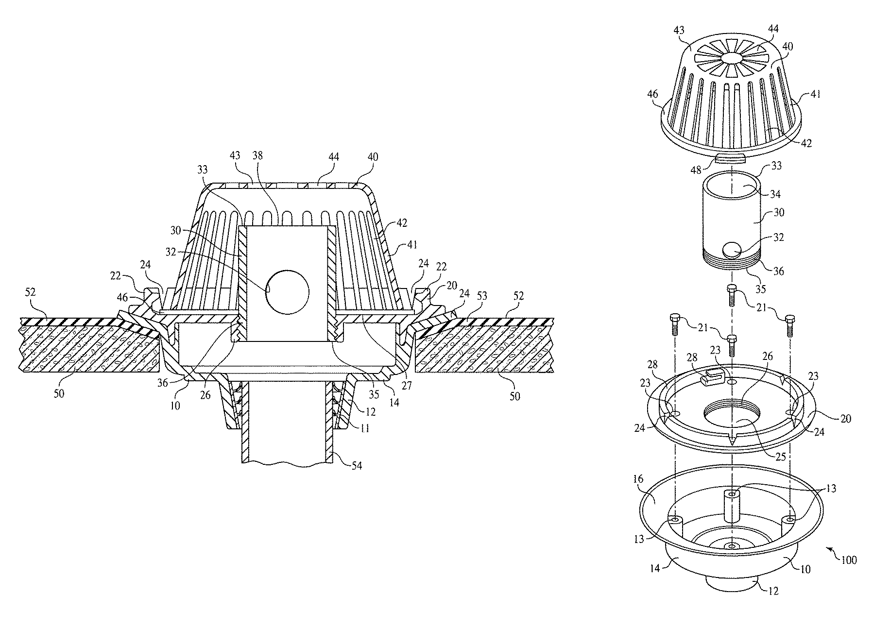
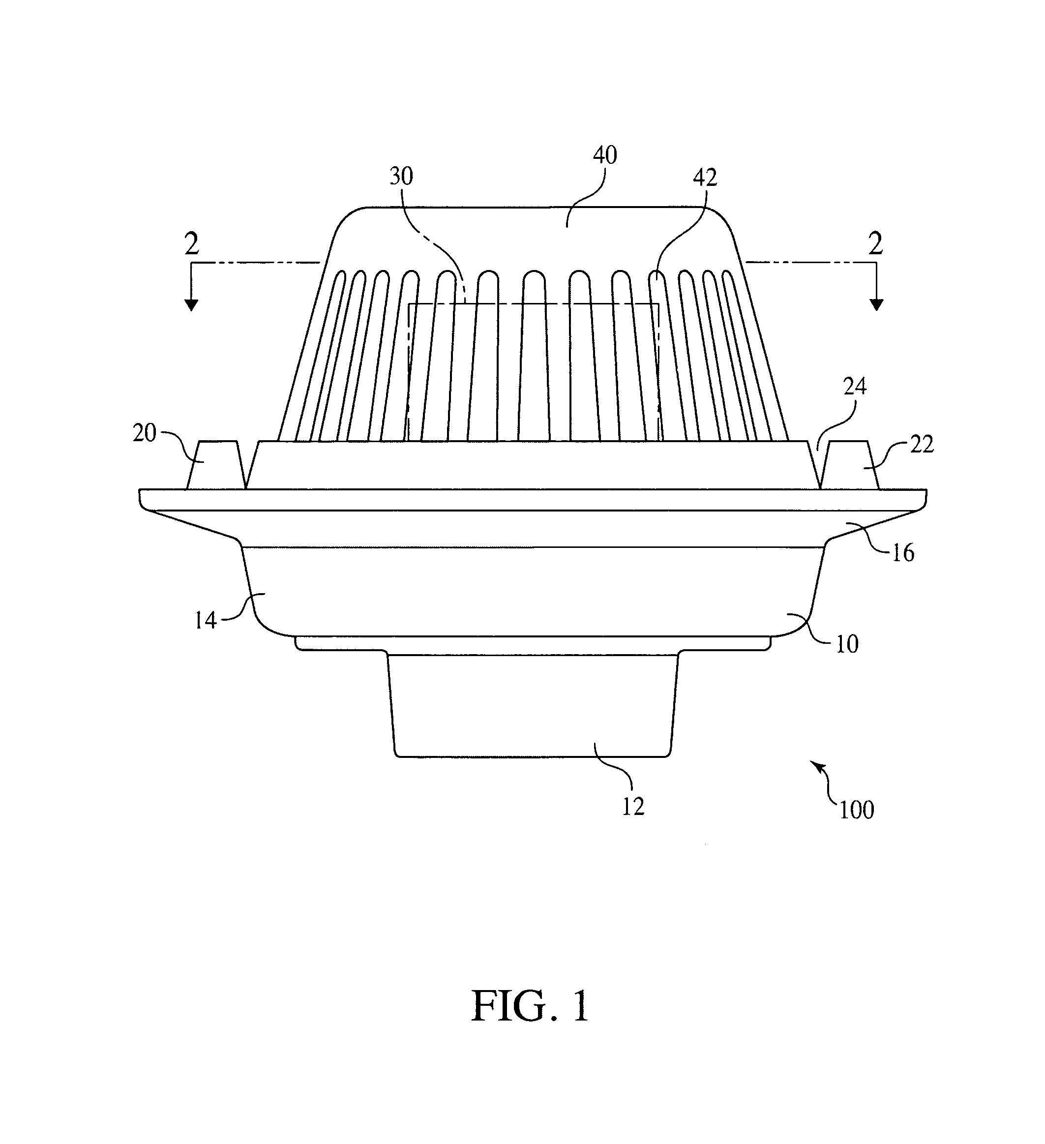
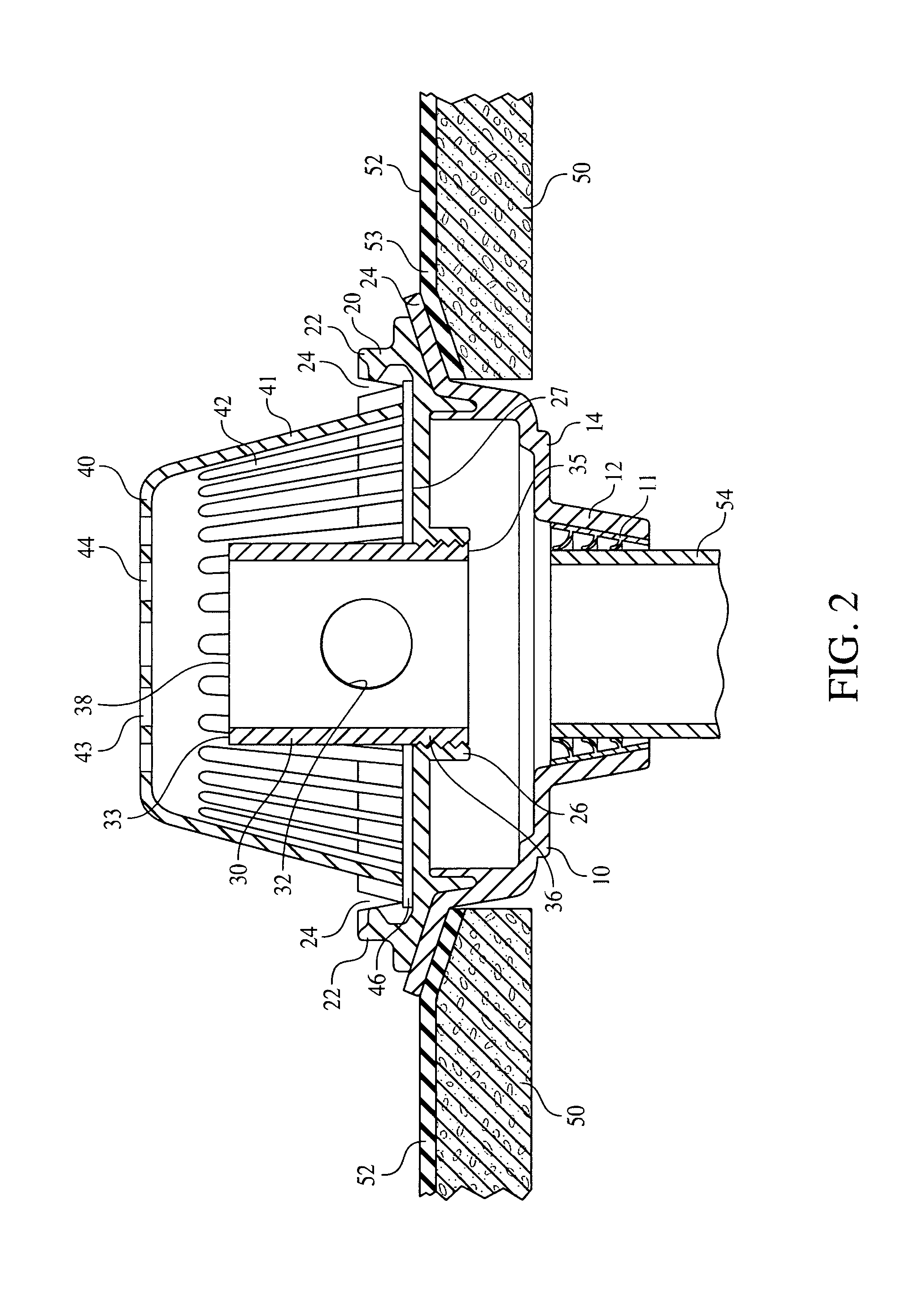
Embodiments include controlled flow rood drains which minimize the size of drainage piping and meet established maximum flow rates by draining built-up water from a flat roof. Embodiments are pre-set by the manufacture in terms of the diameter of the standpipe orifice, which controls maximum flow rate at a predetermined depth of water on the roof, and the height of the standpipe, which determines the depth of water on the roof. Embodiments resist alteration of the flow rate by vandals, tenants, or managers of the building, and are resistant to flow which bypasses the drain control and resistant to plugging by roof debris or snow.
Description
BACKGROUND OF THE INVENTIONField of the Invention[0001]Embodiments relate to roof installed gated inlet surface drains.BRIEF SUMMARY OF THE INVENTION[0002]The efficient drainage of water from flat roofs is an important issue in the construction of commercial buildings. It is important for two reasons to restrict the rate of removal of water from such roofs. Firstly, the capacity of municipal storm sewers often dictate a mandatory limitation on the rate of water which can be removed from a roof and placed in a storm sewer for disposal. Secondly, the cost of drain lines and connector lines which run to the sewer connection constitute a substantial portion of the cost of building manufacture. It is important to minimize the size and thus the cost of these lines.[0003]On the other hand, it is important not to exceed the maximum flow rate for the system. If water is removed from the roof at greater than the design maximum flow rate the system will be overwhelmed, with the risk of backflo...
Claims
Login to View More Application Information
Patent Timeline
 IPC IPC(8): E04D13/04
CPCE04D13/0409E04D2013/0427
Inventor MCDANAL, STEPHEN J.
Owner SMITH IND INC D B A JAY R SMITH MFG CO
Features
- R&D
- Intellectual Property
- Life Sciences
- Materials
- Tech Scout
- Unparalleled Data Quality
- Higher Quality Content
- 60% Fewer Hallucinations
Learn More Browse by: Latest US Patents, China's latest patents, Technical Efficacy Thesaurus, Application Domain, Technology Topic, Popular Technical Reports.
© 2025 PatSnap. All rights reserved.Legal|Privacy policy|Modern Slavery Act Transparency Statement|Sitemap|About US| Contact US: help@patsnap.com