Ocular characteristic device to eliminate ghosting from an IOL during corneal curvature measurement
a technology of iol ghosting and characteristic devices, which is applied in the field of ocular characteristic measuring apparatuses, can solve problems such as lowering measurement accuracy, and achieve the effect of lowering measurement accuracy
- Summary
- Abstract
- Description
- Claims
- Application Information
AI Technical Summary
Benefits of technology
Problems solved by technology
Method used
Image


Examples
first embodiment
[0030]A first embodiment of the present invention will be described in detail with reference to FIGS. 1 to 7. FIG. 1 is an optical system arrangement diagram of a measuring unit of an ocular characteristics measuring apparatus 100a according to the first embodiment of the present invention. An optical system of the ocular characteristics measuring apparatus 100a includes a cornea surface curvature measurement optical system, an ocular refractivity measurement optical system, a fixation target projection optical system, an alignment optical system, and an anterior eye portion observation optical system.
Cornea Surface Curvature Measurement Optical System
[0031]The cornea surface curvature measurement optical system includes a projection system and a light receiving system for the measurement of the cornea surface curvature.
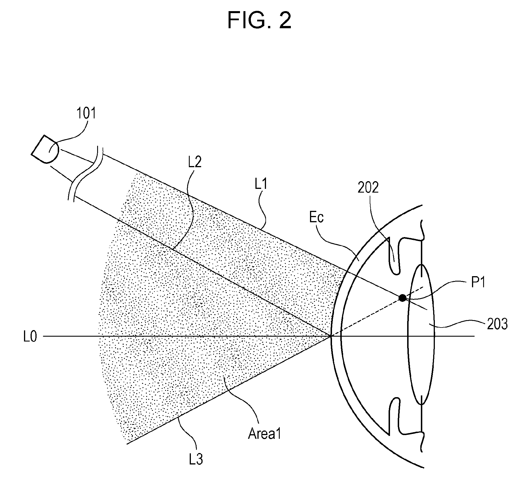
[0032]An optical path 01 from a ring light source 101 to an eye to be examined E is the projection system for the measurement of the cornea surface curvature. The ri...
second embodiment
[0086]Subsequently, a second embodiment of the present invention will be described. Configurations common to those of the first embodiment will be denoted by the same reference numerals as those of the first embodiment and description thereof will be omitted.
[0087]In the first embodiment, it is checked whether the ghost R′ has been generated in the photographed image in the measurement of the cornea surface curvature and the visible light intensity is increased (changed) in accordance with the result. In this configuration, it is difficult to know to what extent the light intensity should be increased for the elimination of the ghost R′. For this reason, there is a possibility that the eye to be examined E undergoes stress by being exposed to unnecessarily intensive visible light. Then, in the second embodiment, the size of the pupil diameter is used as an index, whereby correct measurement of the cornea surface curvature may be performed without increasing the visible light intensi...
third embodiment
[0096]An ocular characteristics measuring apparatus 100c according to a third embodiment has a cornea thickness measuring function in addition to the function of measuring the cornea surface curvature and the ocular refractivity.
[0097]FIG. 10 is an optical system arrangement diagram of a measuring unit of an ocular characteristics measuring apparatus 100c according to the third embodiment of the present invention. An optical system of the ocular characteristics measuring apparatus 100c includes a cornea thickness measurement optical system, a cornea surface curvature measurement optical system, an ocular refractivity measurement optical system, a fixation target projection optical system, an alignment optical system, and an anterior eye portion observation optical system. The optical system of the third embodiment is the same as the optical system of the first embodiment illustrated in FIG. 1 to which the cornea thickness measurement optical system is added, and other configurations...
PUM
 Abstract
Description
Claims
Application Information
 - R&D
- Intellectual Property
- Life Sciences
- Materials
- Tech Scout
- Unparalleled Data Quality
- Higher Quality Content
- 60% Fewer Hallucinations
Browse by: Latest US Patents, China's latest patents, Technical Efficacy Thesaurus, Application Domain, Technology Topic, Popular Technical Reports.
© 2025 PatSnap. All rights reserved.Legal|Privacy policy|Modern Slavery Act Transparency Statement|Sitemap|About US| Contact US: help@patsnap.com