Eureka AIR delivers breakthrough ideas for toughest innovation challenges, trusted by R&D personnel around the world.

Method for improving the illumination of an illuminated area

a technology for improving which is applied in the field of surgical field illumination, surgery, diagnostics, etc., can solve the problems of poor visibility, decreased difficulty in the work of the person, so as to improve the illumination improve the illumination, and reduce the shadowing of the illuminated area.

Active Publication Date: 2016-11-22
DRAGERWERK AG
View PDF11 Cites 3 Cited by
  • Summary
  • Abstract
  • Description
  • Claims
  • Application Information

AI Technical Summary

Benefits of technology

[0006]An object of the present invention is to at least partially eliminate the above-described drawbacks. In particular, the object of the present invention is to make available a method for improving the illumination of an illuminated area, an illuminating device, as well as a use of an illuminating device, which bring about a reliable reduction of the shadowing of the illuminated area due to an improvement of the illumination in a cost-effective and simple manner.

Problems solved by technology

This blocking leads to shadowing or to a partial shadowing of the illuminated area, so that the brightness of the illuminated area decreases.
This will, in turn, lead to worse visibility conditions, which make the work of this person difficult.
This is highly disadvantageous in case of use for surgeons and the illumination of operating areas, because high quality of a surgical procedure is associated with good illumination.
However, the drawback of this prior-art technique is that the proximity sensors have no essential directional characteristic and the position finding of two or more obstacles in the proximity of the light modules may lead to errors.
The consequence of this may be both a slight improvement of illumination and incorrect illumination of the illuminated area.

Method used


Image

  • Method for improving the illumination of an illuminated area
  • Method for improving the illumination of an illuminated area
  • Method for improving the illumination of an illuminated area

Examples


Embodiment Construction

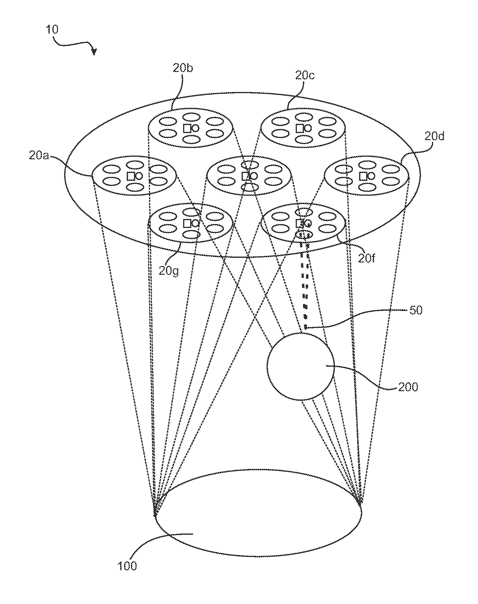
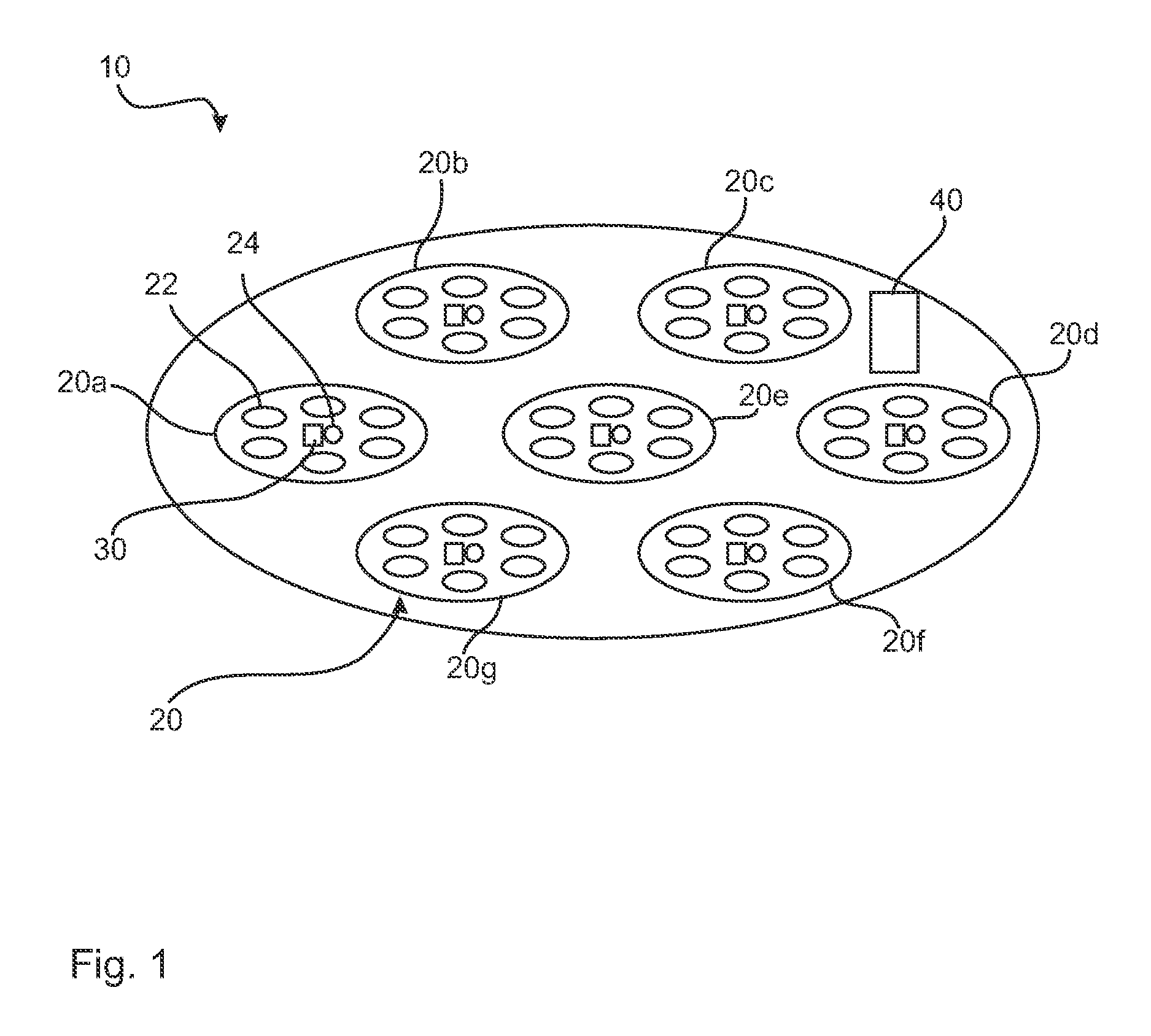
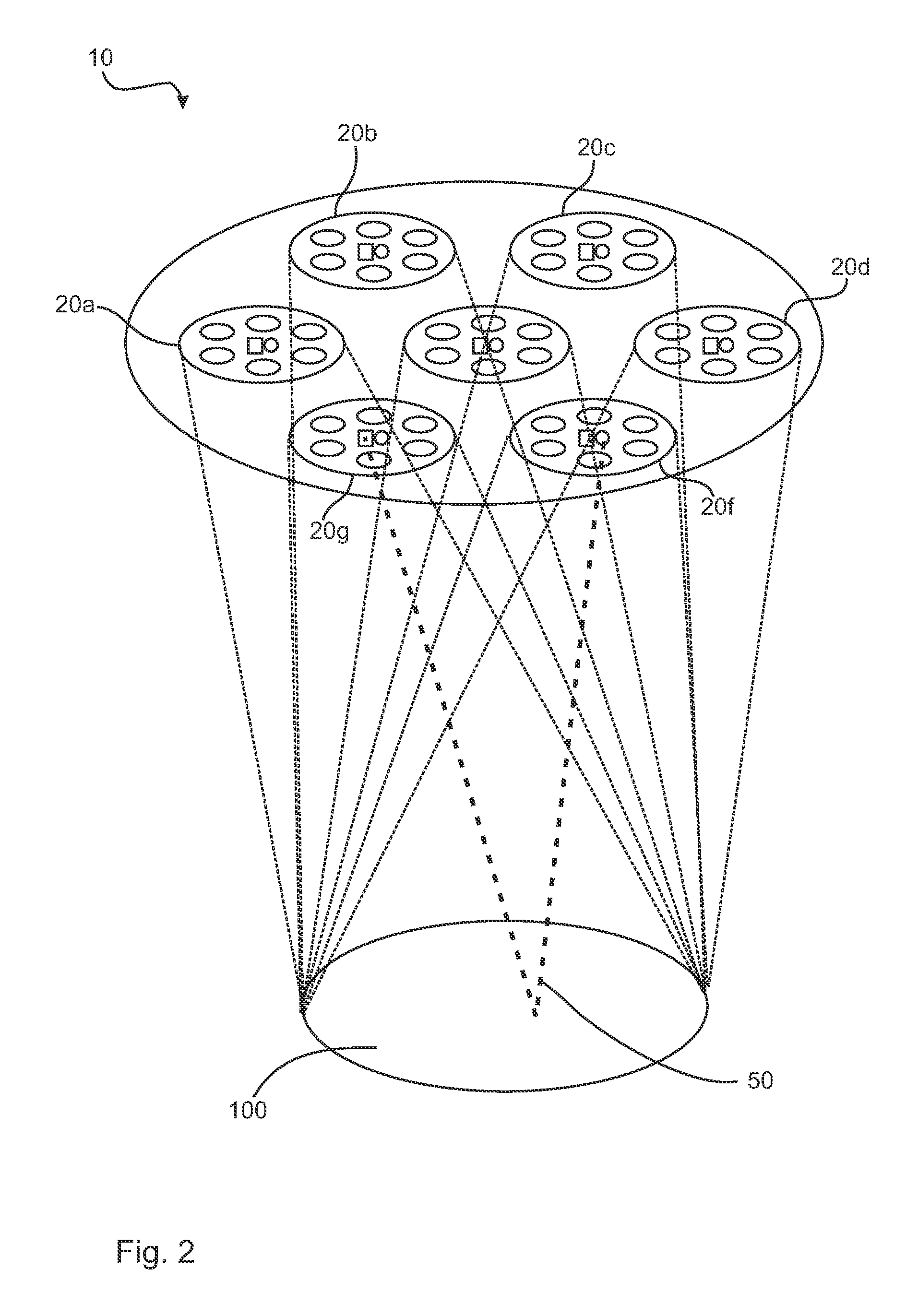
[0049]FIGS. 1 through 3 show a first embodiment of an illuminating device 10 according to the present invention. This is provided with a total of seven light modules 20, which are designated each by individual reference numbers 20a, 20b, 20c, 20d, 20e, 20f and 20g. Each of these light modules 20 is provided with a plurality of illuminating means (illuminants) 22, which are especially LEDs. In addition, a characteristic illuminant 24 each is provided for each light module 20. Each light module 20 likewise has a detector 30. The characteristic illuminant 24 is likewise preferably an LED. In addition, a computer 40 is provided, which can carry out a method according to the present invention.

[0050]FIGS. 2 and 3 show, in principle, the mode of action of a method according to the present invention with an illuminating device 10 according to the present invention. Based on each light module 20, a characteristic light type is thus generated in each characteristic illuminant 24. This charact...


PUM


Abstract

A method is provided for improving the illumination of an illuminated area (100), especially an operating area, of an illuminating device (10) with at least two light modules (20). The method includes the emission of an illuminant characteristic of the light module (20) with a preset amplitude from each light module (20). The reflected amplitudes of all characteristic light types are detected. The detected amplitudes for each light module (20) are compared. The light intensity of at least one light module (20) is varied on the basis of the comparison of the detected amplitudes for each light module (20).

Description

CROSS REFERENCE TO RELATED APPLICATIONS[0001]This application is a United States National Phase Application of International Application PCT / EP2013 / 064357 filed Jul. 8, 2013 and claims the benefit of priority under 35 U.S.C. §119 of German Patent Application DE 10 2012 014 716.3 filed Jul. 25, 2012, the entire contents of which are incorporated herein by reference.FIELD OF THE INVENTION[0002]The present invention pertains to a method for improving the illumination of an illuminated area, to an illuminating device for illuminating an illuminated area, as well as to the use of a corresponding illuminating device.BACKGROUND OF THE INVENTION[0003]Methods for improving illuminated areas and corresponding illuminating devices are, in principle, known. They are used, e.g., to illuminate operating areas during surgical procedures. Such illuminating devices are often provided with at least two light modules, which make the desired illumination available in the direction of the operating area...

Claims


Application Information

Patent Timeline
Patent Type & Authority Patents(United States)
IPC IPC(8): H05B33/08H05B37/02G01J1/32H05B44/00
CPCH05B33/0848A61B90/30H05B37/02H05B37/0218A61B2090/309G01J1/32H05B47/10Y02B20/40H05B45/14H05B47/11
Inventor SATTLER, FRANKFORNASIERO, LIVIOSTARK, HARTMUT
Owner DRAGERWERK AG
Why Eureka
Eureka Blog
Learn More