
Cooling system for liquid crystal display

a liquid crystal display and cooling system technology, applied in the field of cooling systems, can solve the problem of limited space for additional pos advertising

Active Publication Date: 2016-11-22
MFG RESOURCES INT INC
View PDF22 Cites 74 Cited by
  • Summary
  • Abstract
  • Description
  • Claims
  • Application Information

AI Technical Summary

Benefits of technology

The patent describes a cooling system for a transparent LCD assembly. The system uses LEDs placed along the edges of a two-way light guide that allows the light to escape from both sides of the guide. The LEDs are in thermal communication with thermal plates which are in contact with the rear glass. This allows the heat to be transferred out of the system through convection. The technical effect is a more efficient cooling system for transparent displays.

Problems solved by technology

Most retail establishments already contain some POS advertising, and depending on the type of establishment the proprietor may want to limit the amount of ‘clutter’ in the retail area—resulting in a very limited space for additional POS advertising.

Method used


Image

  • Cooling system for liquid crystal display
  • Cooling system for liquid crystal display
  • Cooling system for liquid crystal display

Examples


Embodiment Construction

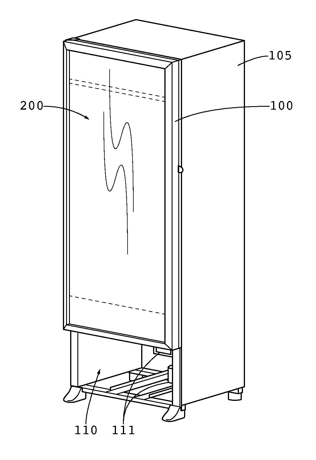
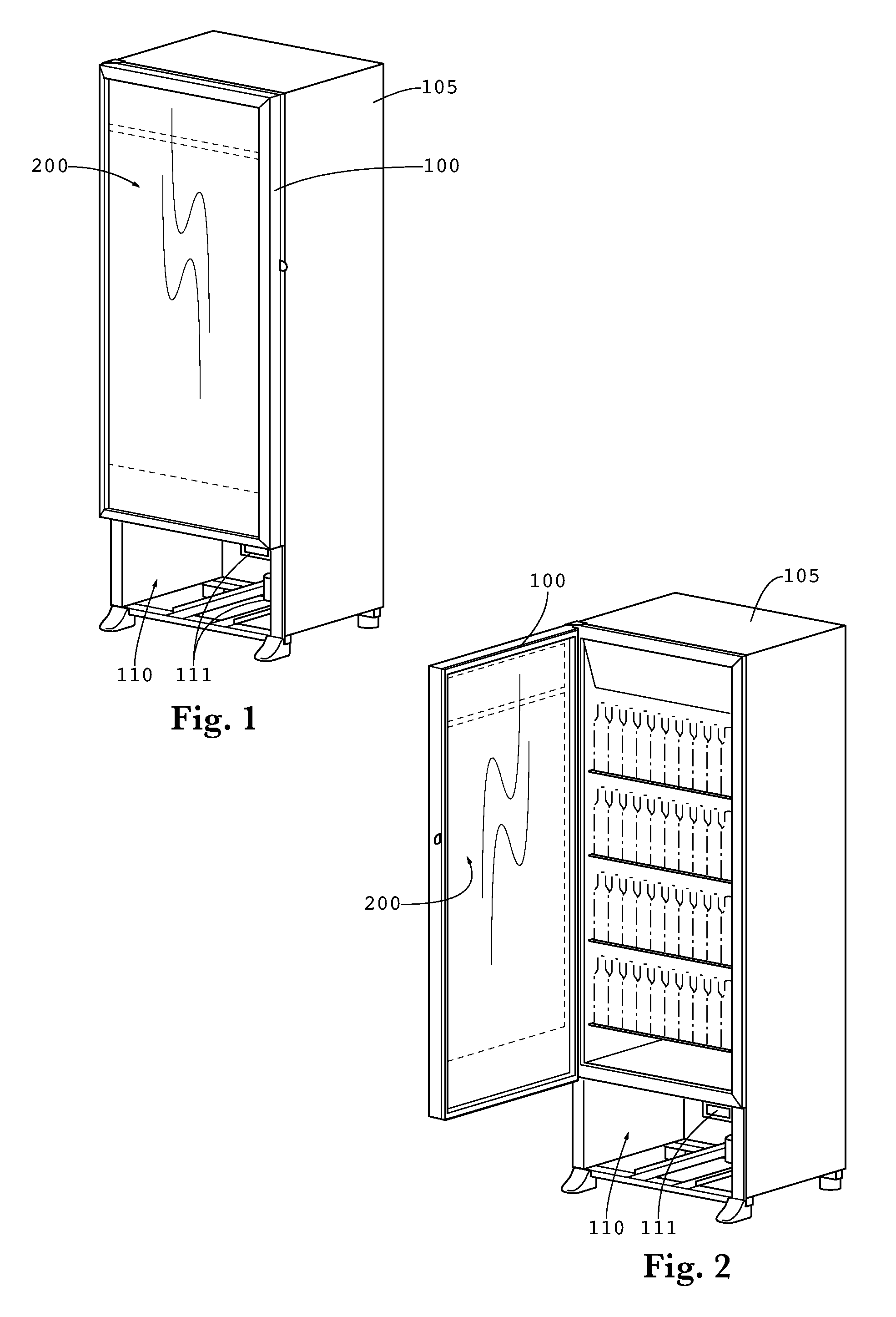
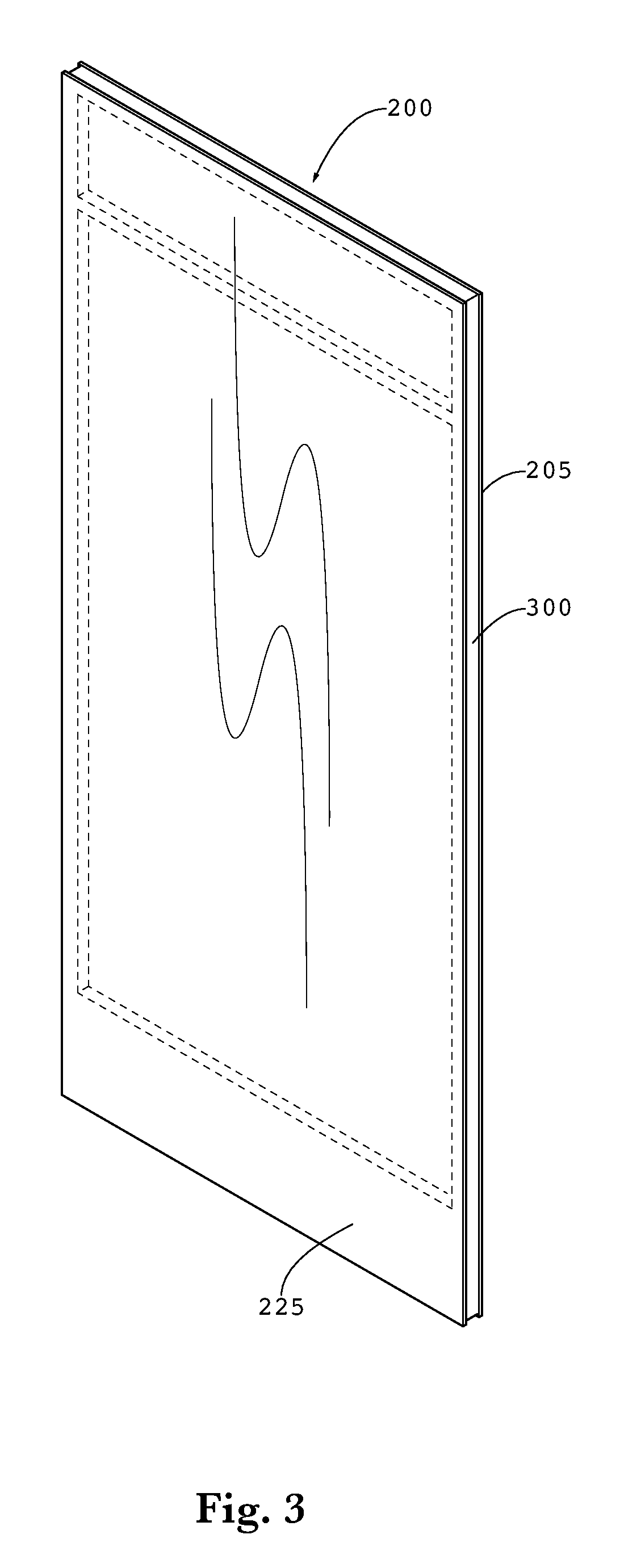
[0005]An exemplary embodiment provides a cooling system for a transparent LCD assembly. LEDs are preferably arranged along the top and bottom edges of a two way light guide which permits the light to exit both the front and rear surface of the light guide. The top LEDs are preferably placed in thermal communication with a top thermal plate which is placed in conductive thermal communication with the rear glass. Similarly, the bottom LEDs are preferably placed in thermal communication with a bottom thermal plate which is also placed in conductive thermal communication with the rear glass. The top and bottom thermal plates permit the heat to spread out and transfer to the rear glass where it can be removed by forced or natural convection.

[0006]The foregoing and other features and advantages of the present invention will be apparent from the following more detailed description of the particular embodiments, as illustrated in the accompanying drawings.

BRIEF DESCRIPTION OF THE DRAWINGS

[0...


PUM

PropertyMeasurementUnit
vertical widthaaaaaaaaaa
transparentaaaaaaaaaa
conductiveaaaaaaaaaa

Abstract

The exemplary embodiments herein provide a transparent liquid crystal display (LCD) assembly having a glass panel with an LCD panel placed in front of the glass panel. A light guide may be positioned between the LCD panel and the glass panel and the light guide may have an edge. A substrate containing a plurality of LEDs is preferably positioned adjacent to the edge of the light guide and a thermal plate is preferably attached to both the substrate and the glass panel. The thermal plate may contain two portions which are substantially perpendicular to each other, where one of the portions is substantially parallel to the glass panel. In some embodiments, the LCD may be sandwiched in between a pair of glass panels, held opposite one another by a spacer.

Description

CROSS-REFERENCE TO RELATED APPLICATIONS[0001]This application claims priority to U.S. Provisional Application No. 62 / 012,785 filed on Jun. 16, 2014 which is herein incorporated by reference in its entirety.TECHNICAL FIELD[0002]Embodiments generally relate to cooling systems for transparent liquid crystal displays (LCD) and traditional LCDs.BACKGROUND OF THE ART[0003]Display cases are used in a number of different retail establishments for illustrating the products that are available for sale. In some instances these display cases may be coolers or freezers which are placed in grocery stores, convenience stores, gas stations, restaurants, or other retail establishments. In other instances these display cases may be non-refrigerated transparent containers used in a jewelry or watch store, bakery, deli, antique shop, sporting goods store, electronics store, or other retail establishments. While the design and appearance of the product itself does provide some point-of-sale (POS) advert...

Claims


Application Information

Patent Timeline
Patent Type & Authority Patents(United States)
IPC IPC(8): G02F1/1333G09F9/35G09F23/06A47F11/10F21V8/00A47B81/06A47F3/04G09F23/00
CPCG02F1/133385A47B81/06A47F3/043A47F3/0434A47F11/10G02B6/0063G02B6/0085G09F9/35G09F23/06G02B6/0095G09F2023/0025G02B6/0068G02B6/0088G02F1/133308G02F1/133615G02F2203/01G09F9/33G02F1/133628
Inventor DUNN, WILLIAMDIAZ, MARCOS
Owner MFG RESOURCES INT INC
Learn More