
Stent system, deployment apparatus and method for bifurcated lesion

a deployment apparatus and stent technology, applied in the field of stent systems, deployment apparatus and methods for bifurcated lesion, can solve the problems of increasing the chance of restenosis, compromising the degree of patency of the primary vessel and/or its branches or bifurcations, and limiting blood flow and access to the side branch vessel

Active Publication Date: 2016-11-08
AL SAADON KHALID
View PDF16 Cites 3 Cited by
  • Summary
  • Abstract
  • Description
  • Claims
  • Application Information

AI Technical Summary

Benefits of technology

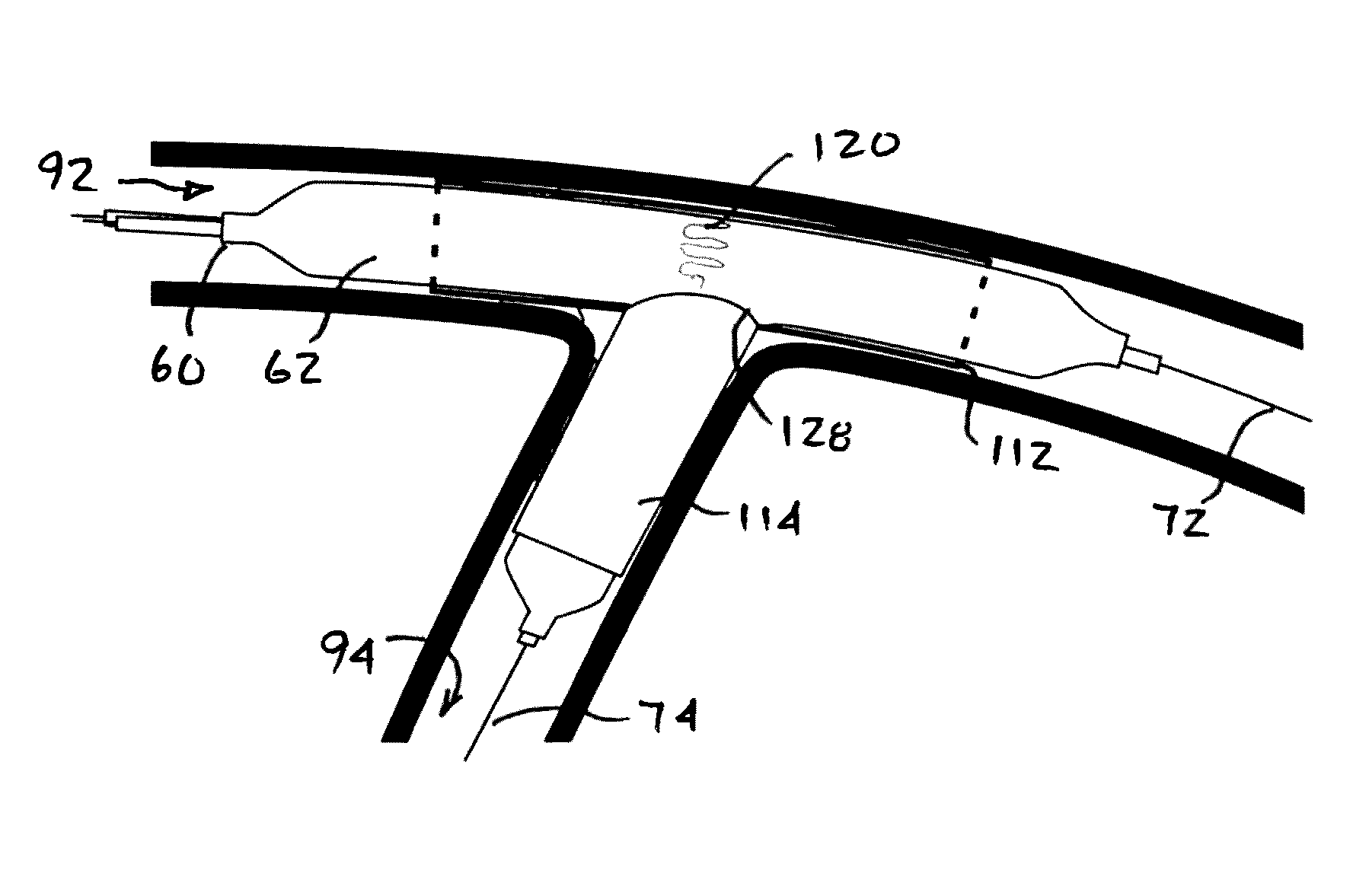
The patent describes an inflatable apparatus for deploying stents in bifurcated vessels. The apparatus has an inflatable side branch portion that can maintain registration with the side branch. The patent also provides methods for deploying stents in bifurcated vessels and a stent system with a special design that allows accurate placement at the bifurcated junction. This technology solves the problem of previous methods that could not effectively treat bifurcated vessels with stents.

Problems solved by technology

One of the drawbacks of the conventional stent techniques is that they run the risk of compromising the degree of the patency of the primary vessel and / or its branches or bifurcation.
This may occur as a result of several problems, such as displacing disease tissue, vessel spasm, and dissection with or without intimal flaps, thrombosis, and embolism, that will increase the chance of restenosis.
These limitations have led others to develop specifically designed stents to treat bifurcation lesions.
U.S. Pat. No. 7,481,834, insertion of traditional stent into a main vessel, after deployment of the new design stent in the side branched stent with anchor design, may pose a limitation to blood flow and access to the side branch vessel.
Another drawback is with the balloon delivery system that assists in positioning the stent with accuracy in the bifurcated lesions, particularly involved in the procedure of double balloon sequential dilation for the stent, which has not proven to be very successful.
This design has its limitations in that it will help to solve specific bifurcation lesions when the distal branches have a Y-shape and the size of the distal vessels are smaller than the size of the proximal vessel (e.g. the aortic artery at bifurcation with iliac arteries) but it is not suitable if the size of one of the distal branches is equal to the proximal vessel size, and not suitable for the side branched vessels which are the majority of the cases.

Method used


Image

  • Stent system, deployment apparatus and method for bifurcated lesion
  • Stent system, deployment apparatus and method for bifurcated lesion
  • Stent system, deployment apparatus and method for bifurcated lesion

Examples


Embodiment Construction

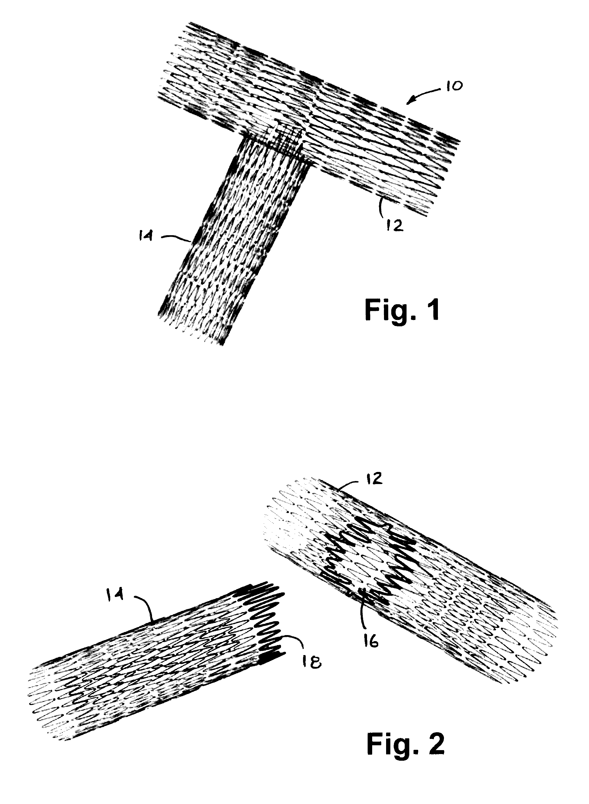
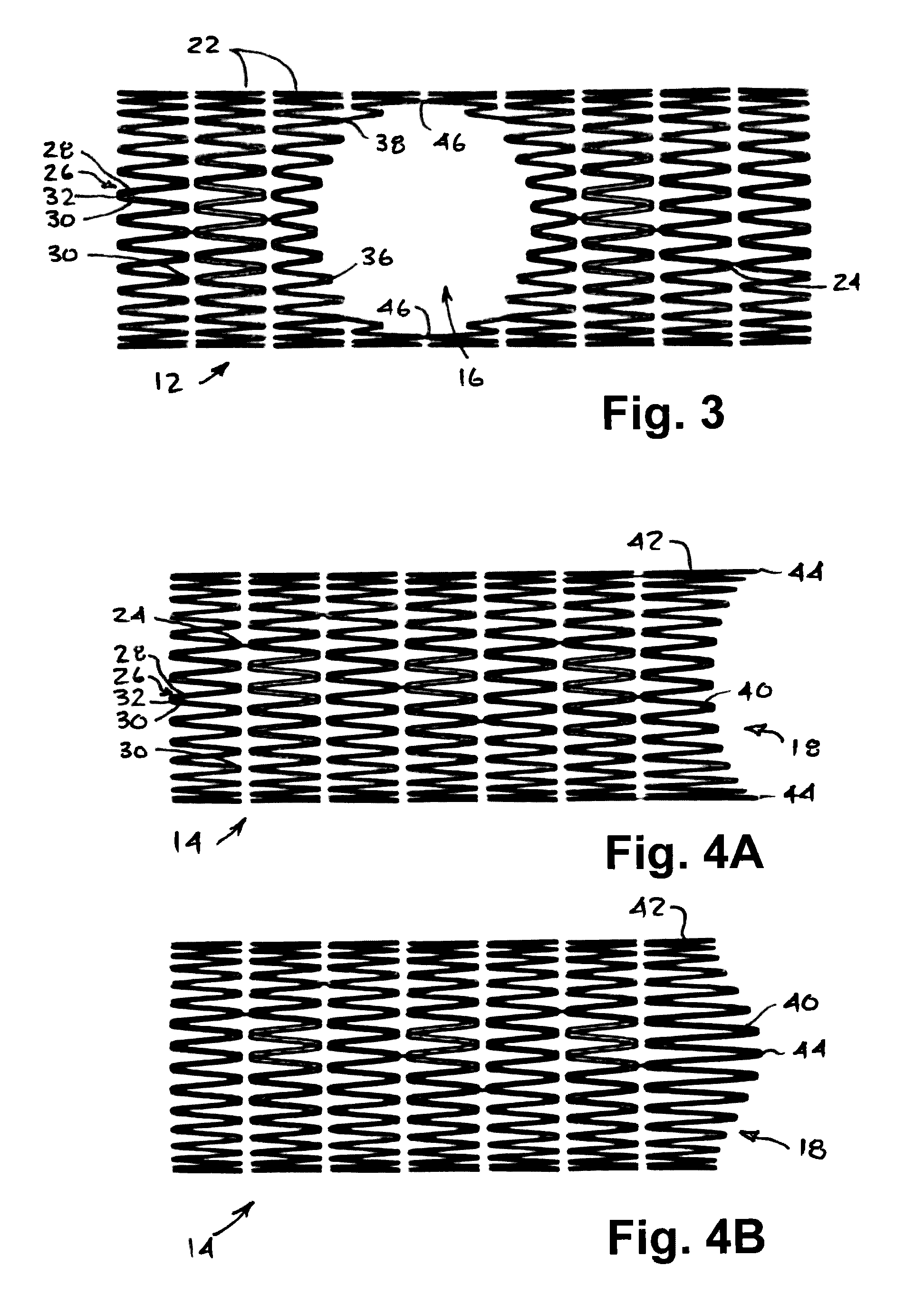
[0074]With reference to FIGS. 1 and 2, an embodiment of a bifurcated stent system 10 according to the invention is illustrated. The bifurcated stent system 10 comprises a generally tubular main stent 12 and a generally tubular side branch stent 14. The main stent 12 is provided with a side opening 16 in its cylindrical wall matrix adapted to engage and mate with the proximal end 18 of the side branch stent 14. In general, when expanded, the side branch stent 14 has an end shape which complements the opening 16 in the main stent 12, which minimizes the over-entanglement of stent wires when the stents have been cooperatively expanded, thereby minimizing the potential of obstruction of blood flow at or near the juncture. The opening 16 may be circular, elliptical, diamond-shaped or may closely approximate the intersection of two cylinders at various geometries. Although the side branch stent 14 is shown in FIG. 1 as extending approximately 90° from the main stent 12, the stents 12,14 m...


PUM


Abstract

A deployment apparatus and method for deploying one or more stents to a bifurcated vessel is provided. The invention is particularly suited for T-type bifurcated vessels where a side branch extends from a main branch. The deployment apparatus has a primary inflatable portion for engagement within the main branch and a secondary inflatable portion for engagement within the side branch. A main stent is arranged on the primary inflatable portion and radially expanded within the main branch while the secondary inflatable portion maintains registration with the side branch. A side branch stent is then arranged on the secondary inflatable portion and expanded within the side branch while the primary inflatable portion maintains registration with the expanded main stent. A bifurcated stent system suitable for bifurcated lesions is also provided comprising a side branch stent with a shaped end designed to engage a similarly shaped side opening in a main stent.

Description

FIELD OF THE INVENTION[0001]The present invention relates to a deployment apparatus and method for deploying one or more stents to a bifurcated vessel. The deployment apparatus is particularly suited for bifurcated vessels of the type comprising a main branch from which a side branch extends therefrom. The invention is also related to a bifurcated stent system suitable for use in bifurcated vessels.BACKGROUND OF THE INVENTION[0002]The term stent has been used interchangeably with terms such as intraluminal vascular graft and expansible prosthesis. As used throughout this specification, the term stent is intended to have a broad meaning and encompasses any expandable prosthetic device for implantation in a body passageway (e.g. a lumen or artery).[0003]There have been various attempts at addressing the delivery and deployment of stents at bifurcated lesions. Bifurcated vessels may be of the Y-type, wherein a main branch bifurcates into two secondary branches, or of the T-type, wherei...

Claims


Application Information

Patent Timeline
Patent Type & Authority Patents(United States)
IPC IPC(8): A61F2/954A61F2/856A61F2/958A61F2/82A61F2/915
CPCA61F2/954A61F2/856A61F2/958A61F2002/821A61F2002/828A61F2002/91558A61F2250/0007A61F2230/006A61F2230/0069
Inventor AL-SAADON, KHALID
Owner AL SAADON KHALID
Learn More