Shaker apparatus and related methods of transmitting vibrational energy to recipients
a shaker and receiver technology, applied in mechanical vibration separation, tactile signalling system, signalling system, etc., can solve the problems of body wear, overly energetic sounds, damage to listener's hearing,
- Summary
- Abstract
- Description
- Claims
- Application Information
AI Technical Summary
Benefits of technology
Problems solved by technology
Method used
Image
Examples
Embodiment Construction
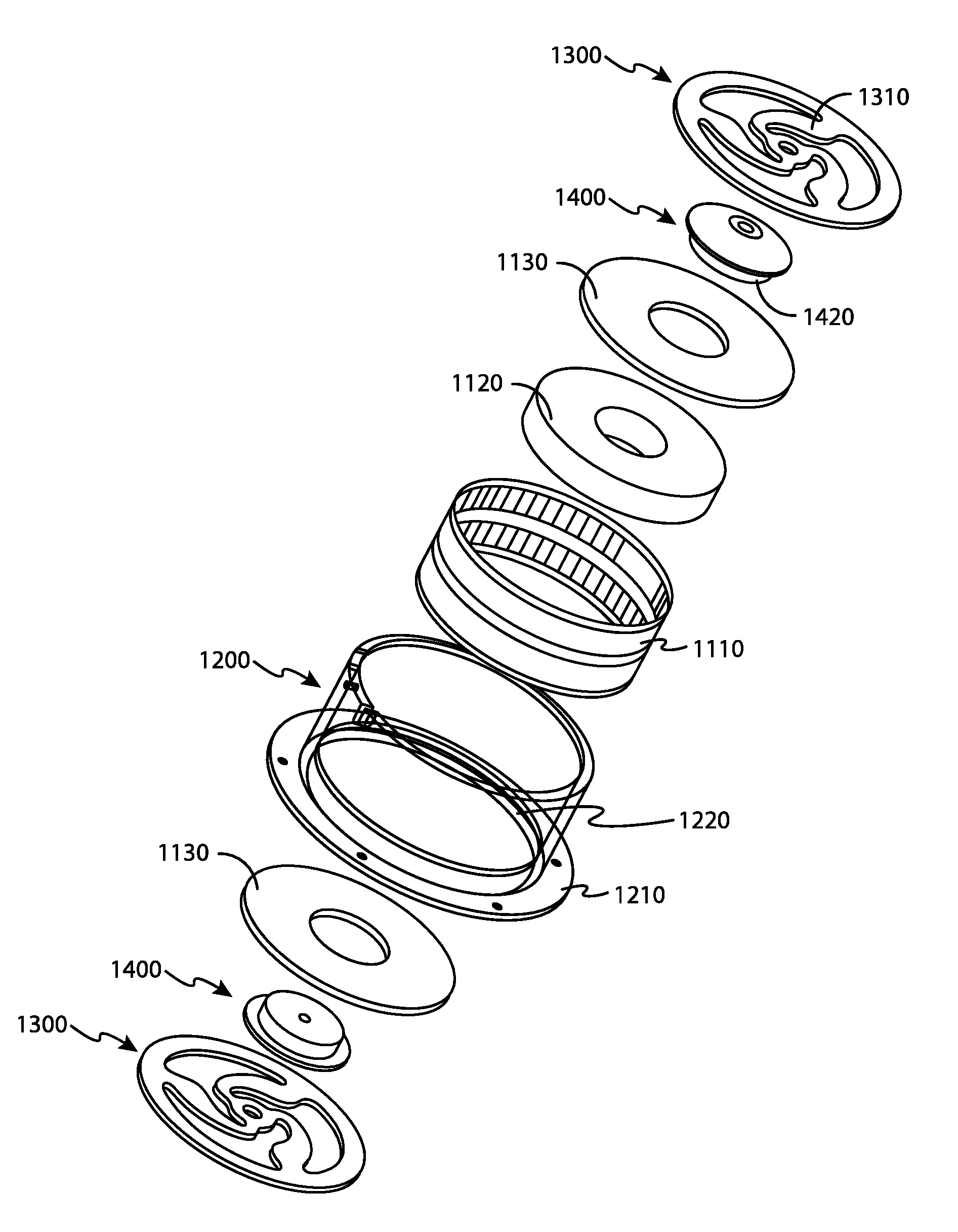
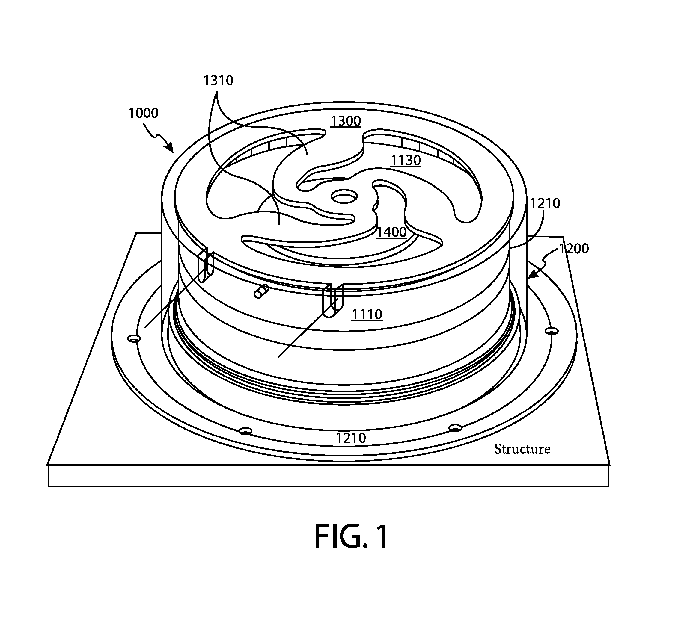
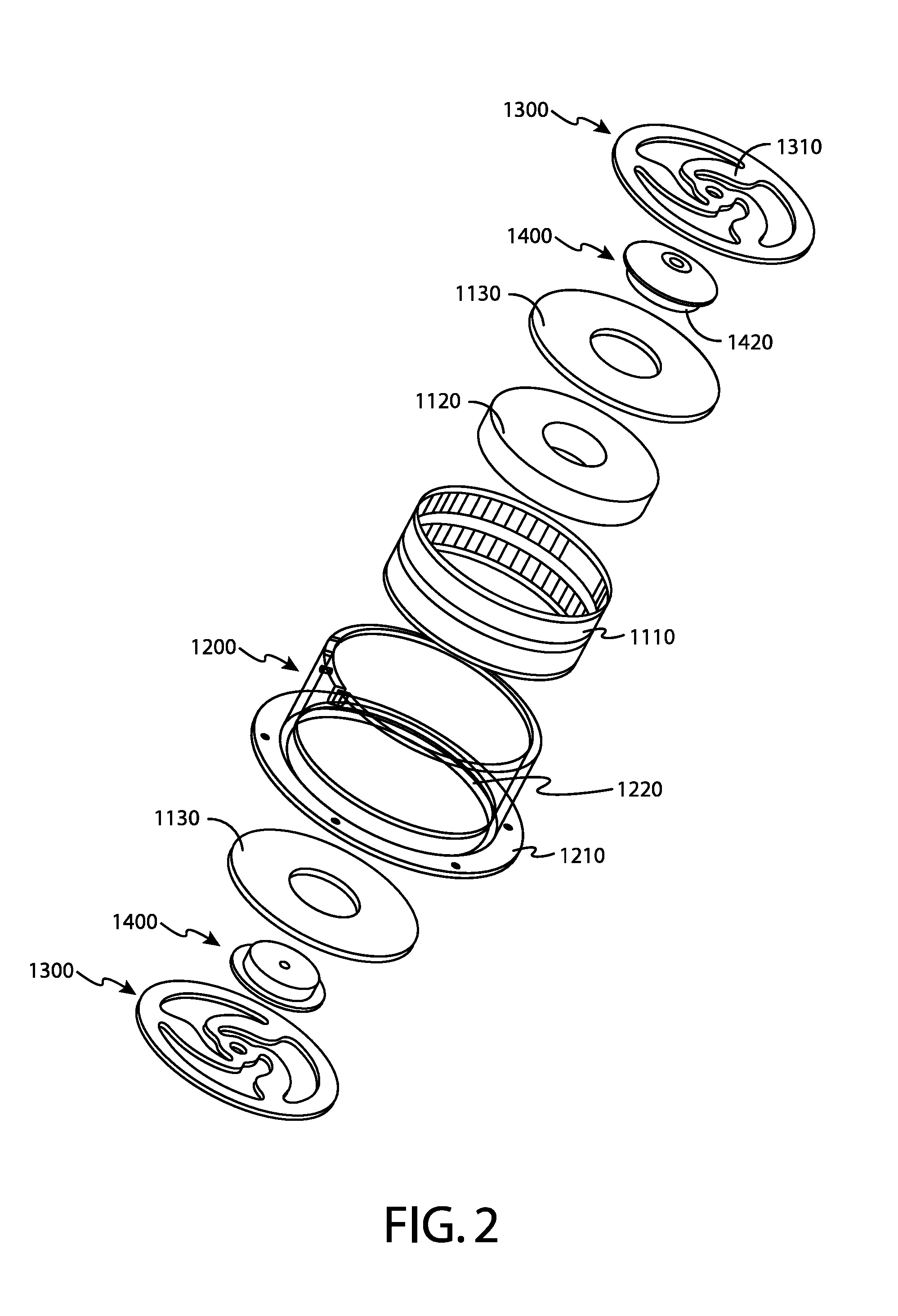
[0040]FIG. 1 is a see-through perspective view of a preferred embodiment of a shaker 1000. FIG. 2 is an exploded view of the shaker 1000 shown in FIG. 1. FIG. 3 is a cross section of the shaker 1000 of FIG. 1. As shown in FIGS. 1 through 3, the shaker 1000 comprises: a housing 1200 (shown in FIGS. 1 through 3) that is defined by a flange 1210 and a sidewall 1220; a shaker motor 1100 that is defined by a wire coil 1110 (shown in FIGS. 1 through 3), a magnet 1120 (shown in FIGS. 2 and 3), and two pole plates 1130 (shown in FIGS. 2 and 3) occupying the poles of the magnet 1120 (shown in FIGS. 2 and 3); two distance holders 1400 (shown in FIGS. 2 and 3); and two spyder disks 1300 with three spokes 1310.
[0041]In operation, the shaker motor 1100 creates mechanical vibrations of sounds. In a preferred embodiment, the motor 1100 produces vibrations via passing a controlled electric current representing sounds through the wire coil 1110 positioned around the movable magnet 1120. Preferably, ...
PUM
 Abstract
Description
Claims
Application Information
 - R&D Engineer
- R&D Manager
- IP Professional
- Industry Leading Data Capabilities
- Powerful AI technology
- Patent DNA Extraction
Browse by: Latest US Patents, China's latest patents, Technical Efficacy Thesaurus, Application Domain, Technology Topic, Popular Technical Reports.
© 2024 PatSnap. All rights reserved.Legal|Privacy policy|Modern Slavery Act Transparency Statement|Sitemap|About US| Contact US: help@patsnap.com


