
Disengageable axial thrust bearing with internal preload

a technology of axial thrust bearing and internal preload, which is applied in the direction of rotary bearings, rolling contact bearings, shafts and bearings, etc., can solve the problems of affecting reducing the life of the bearing, so as to facilitate the operation and facilitate the bearing design. , the effect of simple operation

Active Publication Date: 2016-11-01
SN DETUDE & DE CONSTR DE MOTEURS DAVIATION S N E C M A
View PDF10 Cites 0 Cited by
  • Summary
  • Abstract
  • Description
  • Claims
  • Application Information

AI Technical Summary

Benefits of technology

The patent text describes a new design for an axial thrust bearing that allows for smoother operation and better control over the transition between different points of contact. This is achieved by adding a second pre-loading system that helps to avoid operating with three points of contact for long periods of time, which can damage the bearing. Overall, the new design improves the performance and durability of the bearing.

Problems solved by technology

This gap is thus particularly complex to define since it requires good control over the external / internal loading of the bearing and over the associated deformation, such as the deflection of the bearing under load, the ½ BE compression under pre-loading, or indeed taking account of the effects of centrifuging.
Another drawback results from calibrating the pre-loading system 10.
The operation of the bearing can then become unstable temporarily (operating with three points of contact, balls sliding, or indeed contact being lost), which is particularly harmful to its lifetime.
That also requires good knowledge of how the axial force from the rotor varies as a function of the speed of rotation, which is particularly difficult to determine during the stage in which the speed of rotation of the shaft is varying quickly and in which the rotary machine might be operating under conditions that are very different from its nominal conditions.
Yet another drawback is that the prior art axial thrust bearing is particularly complex to manufacture.
That leads to very tight manufacturing tolerances being defined for the tracks of the outer ring of the bearing, thus making it difficult and expensive to manufacture in practice.

Method used


Image

  • Disengageable axial thrust bearing with internal preload
  • Disengageable axial thrust bearing with internal preload
  • Disengageable axial thrust bearing with internal preload

Examples


Embodiment Construction

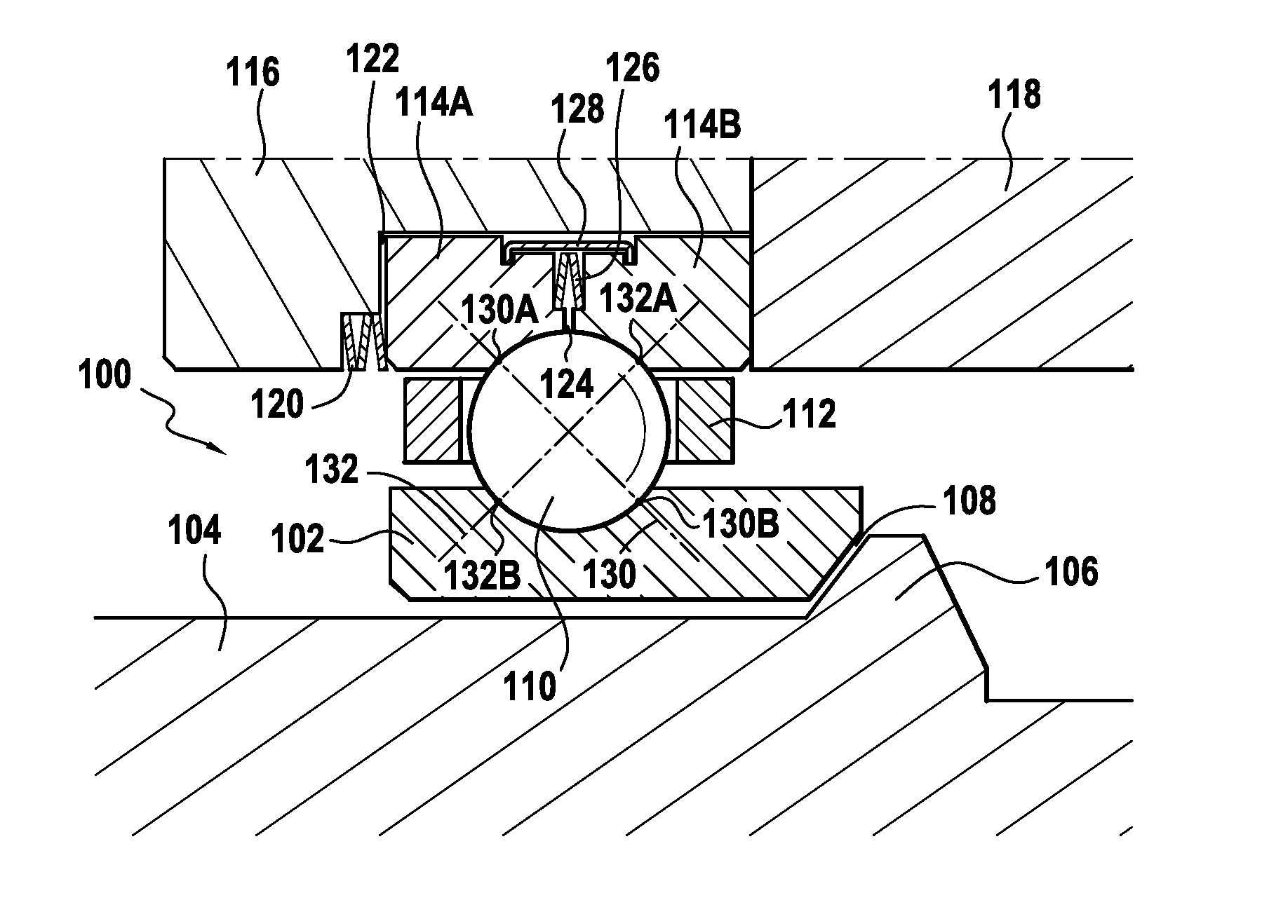
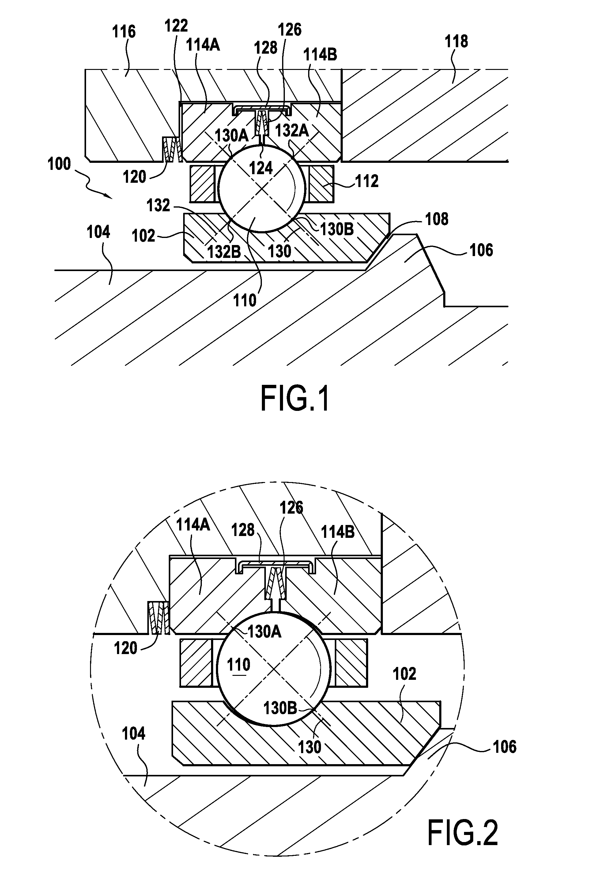
[0023]FIG. 1 shows an embodiment of a disengageable axial thrust bearing of the invention. The thrust bearing 100 comprises an inner ring 102 mounted in radially non-interfering manner on a central shaft 104 that may be secured to an impeller of a cryogenic rotary machine, for example. The central shaft is advantageously mounted on conventional bearings, of fluid type, of leaf type, of magnetic type, or of other type, not shown in the drawing, and the rotary machine is advantageously fitted with a system for providing active axial balancing under steady conditions.

[0024]Examples of systems for active axial balancing are described by way of example in patent documents FR 2 698 666 and FR 2 698 667.

[0025]The inner ring 102 is provided with rotary drive by a synchronization element 106 that, in the absence of axial loading, is spaced apart from the inner ring by first clearance 108 of the order of a few hundredths of a millimeter to several millimeters.

[0026]The axial thrust bearing ha...


PUM


Abstract

In a disengageable axial thrust bearing for a rotary machine, an outer ring has first and second outer half-rings (114A, 114B) centered in a casing (116) and clamped in the axial direction between a stationary thrust member (118) and a first pre-loading system (120) exerting a first predetermined axial force such that, so long as the axial load exerted on the axial thrust bearing via a synchronization element (106) is greater than a determined threshold value, rolling elements (110) with oblique contacts present respective single lines (130) having two points of contact (130A, 130B) with an inner ring (102) and with the first outer half-ring (114A), the second outer half-ring (114B) being spaced apart from the first by a second predetermined axial force exerted by a second pre-loading system (126) inserted in the axial direction between the first and second outer half-rings, and such that the inner ring (102) is driven in rotation by the synchronization element, whereas, when the axial load exerted on the axial thrust bearing becomes less than this determined threshold value, a second line (132) having two additional points of contact (132A, 132B) is created between each of the oblique-contact rolling elements (110) and the inner ring (102) and the second outer half-ring (103B) such that the axial thrust bearing is disengaged.

Description

[0001]This application is the U.S. national phase entry under 35 U.S.C. §371 of International PCT Application No. PCT / FR2014 / 050699, filed on Mar. 25, 2014, which claims priority to French Patent Application No. FR 1352806, filed on Mar. 28, 2013, the entireties of each of which are incorporated by reference herein.FIELD OF THE INVENTION[0002]The present invention relates to a disengageable axial thrust bearing for a rotary machine, the thrust bearing comprising an inner ring arranged around a rotary shaft in radially non-interfering manner on said shaft, a synchronization element mounted on the rotary shaft for driving the inner ring selectively in rotation, an outer ring made up of two half-rings slidably mounted in a casing, and oblique-contact rolling elements.PRIOR ART[0003]In the context of cryogenic rotary machines mounted on radial fluid bearings, where one of the major advantages of such machines is long lifetime in comparison with machines mounted on conventional ball or r...

Claims


Application Information

Patent Timeline
Patent Type & Authority Patents(United States)
IPC IPC(8): F16C25/08F16C33/60F16C19/16F16C19/10F16C39/02F16C27/08
CPCF16C25/083F16C19/10F16C19/166F16C33/60F16C27/08F16C39/02
Inventor BOUFFLERT, SEBASTIENBOURDIN, PHILIPPELEMAITRE, ALBANTESSIER, FABIEN
Owner SN DETUDE & DE CONSTR DE MOTEURS DAVIATION S N E C M A
Learn More