
Maintenance information device, condition sensor for use therein and method which can be carried out therewith for arriving at a decision whether or not to perform servicing or maintenance

a technology of condition sensor and maintenance information, which is applied in the direction of electric testing/monitoring, process and machine control, instruments, etc., can solve the problems of an expected increase in maintenance work, particularly maintenance-intensive technology, and distant objectives which cannot yet be implemented, so as to reduce entropy, complex design, and increase development and operating costs

Active Publication Date: 2016-10-25
EADS DEUT GMBH
View PDF20 Cites 2 Cited by
  • Summary
  • Abstract
  • Description
  • Claims
  • Application Information

AI Technical Summary

Benefits of technology

The invention provides an algorithm for making decisions based on data from imperfect sensors. This algorithm helps predict the future wear behavior of condition-monitored components or systems, which can better decision-making. The invention also proposes using hyperordinal sensors, which generate definitive information with significantly reduced entropy but remain largely precise in the significant definitive information. This reduces the complexity of design and cost compared to traditional sensors. The algorithm allows for reliable determination of the remaining useful life of a system based on very imprecise definitive information.

Problems solved by technology

Condition-based maintenance is also of interest, in particular, in the field of aircraft technology since such technology is particularly maintenance-intensive owing to the relevance of the technical systems used to safety.
However, this is a distant objective which cannot yet be implemented owing to the shortcomings of the devices and methods known hitherto for monitoring conditions and performing maintenance.
With aircraft technology there is also the problem of an expected increase in maintenance works since new materials, such as force-flux-compatible composite fiber materials, are being increasingly used in the construction of aircraft in order to save weight.
In particular in the case of fiber-reinforced composite materials it is, however, possible for wear phenomena and invisible internal damage to occur in the case of relatively heavy loading, with the result that an exchange of components made of fiber-reinforced composite materials is indicated after specific scopes of operation and degrees of loading before these components fail.
However, the main disadvantage of CBM is that the initial costs of CBM are very high.
The costs of adequate measuring technology are usually very high; this also applies specifically to equipment which has already been installed.
However, even when pieces of technical equipment and systems with the previously known condition sensors and evaluation technologies are re-developed, high additional costs are incurred, with the result that condition-based maintenance could previously be implemented only on a small number of main components of technical systems.
However, condition monitoring with perfect sensors can be applied to real systems only to a restricted degree.
The calculation of the RUL is very complex depending on the application and increases the implementation costs.
It is known, for example from the abovementioned literature and patent literature, that high to prohibitive costs are incurred by the development of CBM sensors and, above all, the algorithms which calculate the remaining useful life from acquired physical data of the sensors.
This is due to the fact that the sensor attempts to determine the most precise remaining useful life possible at any time between the equipment being put into service and its failure.
The developer of the sensor does not know how well the calculation of the remaining useful life has to be effective at specific intervals, with the result that he does not have any possibility to optimize.
While there are no perfect sensors in reality, classic sensors are more complex in design compared to the hyperordinal sensors proposed according to one preferred embodiment of the invention, and entail correspondingly higher development and operating costs.

Method used


Image

  • Maintenance information device, condition sensor for use therein and method which can be carried out therewith for arriving at a decision whether or not to perform servicing or maintenance
  • Maintenance information device, condition sensor for use therein and method which can be carried out therewith for arriving at a decision whether or not to perform servicing or maintenance
  • Maintenance information device, condition sensor for use therein and method which can be carried out therewith for arriving at a decision whether or not to perform servicing or maintenance

Examples


Embodiment Construction

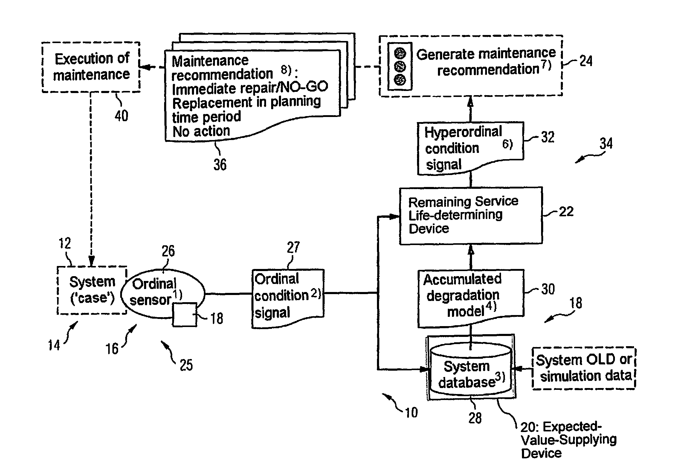
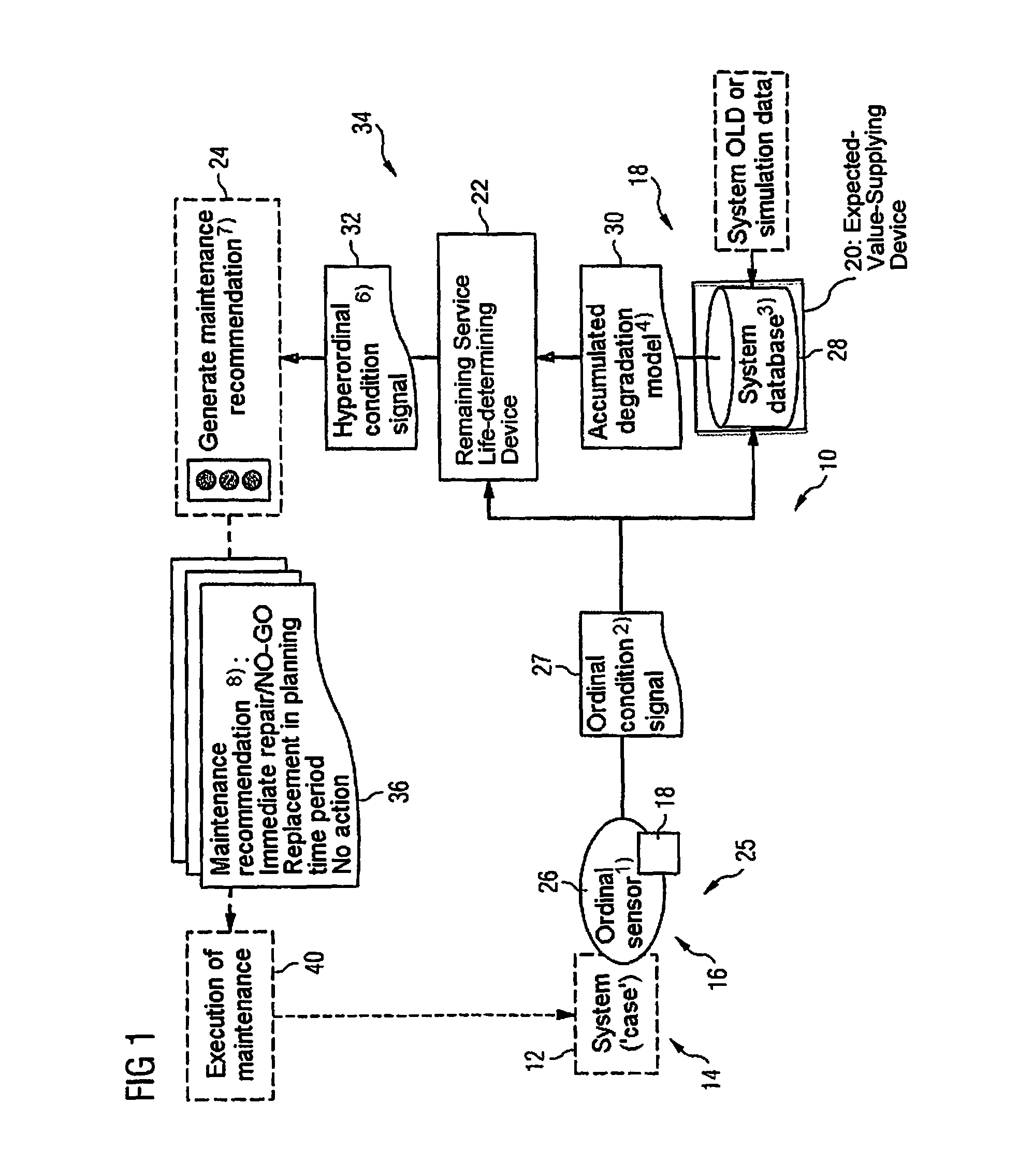
[0050]FIG. 1 is a schematic illustration of a maintenance information device 10 and of a flowchart for the functioning thereof in the form of an algorithm which is illustrated as a block diagram. The maintenance information device 10 serves to supply information for arriving at a decision as to whether or not maintenance should be performed on a condition-monitored technical system 12.

[0051]The technical system 12 can be any equipment or component which has to be maintained. Examples of such technical systems can be found in the literature and patent literature on condition-based maintenance which is mentioned at the beginning. In one preferred exemplary embodiment, the monitored technical system 12 is a component 14 or a piece of equipment of an aircraft. Examples of such components are structural elements of the rear or of wings or of tailplane fins, propulsion units or propulsion unit components, air conditioning systems, cooling systems, life support systems, rescue equipment, c...


PUM


Abstract

A maintenance information device and method for performing condition-based maintenance by monitoring of the condition of a technical system using a sensor. In order to permit the use of relatively simple sensors with relatively simple evaluation logics, the method and device perform decision making processes on the basis of hyperordinal signals from imperfect hyperordinal condition sensors.

Description

CROSS-REFERENCE TO RELATED APPLICATIONS[0001]This U.S. National stage application claims priority under 35 U.S.C. §119(a) to German Patent Application No. 10 2010 049 909.9, filed on Oct. 28, 2010, the entire contents of German Patent Application No. 10 2010 049 909.9 are hereby incorporated herein by reference.BACKGROUND[0002]1. Field of the Invention[0003]The invention relates to a device and a method for assisting a decision whether or not servicing or maintenance of a system whose condition is monitored by means of a condition sensor is to be carried out. Furthermore, the invention relates to a condition sensor which can be used in such a device or in such a method.[0004]2. Background Information[0005]The invention is in the field of condition-based maintenance (CBM). In brief, CBM means that servicing or maintenance is carried out when there is a need for it. The servicing or maintenance is carried out when an indicator or a plurality of indicators show that the monitored equip...

Claims


Application Information

Patent Timeline
Patent Type & Authority Patents(United States)
IPC IPC(8): G05B23/02
CPCG05B23/0208G05B23/0283G05B2219/32234
Inventor SCHRAMM, GERRITSCHIRRMANN, ARNDZOLLER, KLAUS
Owner EADS DEUT GMBH
Learn More