Plasmon generator including a main body and a front protrusion

Active Publication Date: 2016-10-18
HEADWAY TECH INC
View PDF11 Cites 8 Cited by
  • Summary
  • Abstract
  • Description
  • Claims
  • Application Information

AI Technical Summary

Benefits of technology

This patent describes a plasmon generator that improves the dissipation of heat and the generation of near-field light. It also allows for precise control of the width of the near-field light generating surface. This plasmon generator is useful in a thermally-assisted magnetic recording head.

Problems solved by technology

Making the magnetic fine particles smaller, however, causes the problem that the magnetic fine particles drop in the thermal stability of magnetization.
However, increasing the anisotropic energy of the magnetic fine particles leads to an increase in coercivity of the recording medium, and this makes it difficult to perform data writing with existing magnetic heads.
A thermally-assisted magnetic recording head suffers from the problem that heat generated by the plasmon generator causes the plasmon generator to shrink and become distant from the medium facing surface, and also causes the main pole to be corroded, which result in a shorter life of the thermally-assisted magnetic recording head.
In the plasmon generator disclosed in U.S. Patent Application Publication No. 2011 / 0170381 A1, heat generated at the narrow portion, particularly at the near-field light generating surface, may cause the narrow portion to shrink and become distant from the medium facing surface, and consequently cause the plasmon generator to become unable to form a sport of near-field light on a recording medium.
Conventionally, however, any attempts to reduce the neck height have resulted in difficulty in accurately controlling the width of the near-field light generating surface.

Method used


Image

  • Plasmon generator including a main body and a front protrusion
  • Plasmon generator including a main body and a front protrusion
  • Plasmon generator including a main body and a front protrusion

Examples


first embodiment

[0072]Preferred embodiments of the present invention will now be described in detail with reference to the drawings. First, reference is made to FIG. 5 to FIG. 11 to describe the configuration of a thermally-assisted magnetic recording head according to a first embodiment of the invention. FIG. 5 is a perspective view showing the main part of the thermally-assisted magnetic recording head. FIG. 6 is a cross-sectional view showing the main part of the thermally-assisted magnetic recording head. FIG. 7 is a front view showing the main part of the thermally-assisted magnetic recording head. FIG. 8 is a cross-sectional view showing the configuration of the thermally-assisted magnetic recording head. FIG. 9 is a front view showing the medium facing surface of the thermally-assisted magnetic recording head. FIG. 10 is a plan view showing a first layer of a coil of the present embodiment. FIG. 11 is a plan view showing a second layer of the coil of the present embodiment.

[0073]The thermall...

modification examples

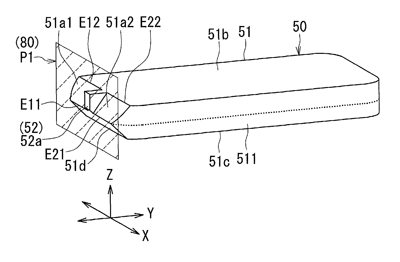
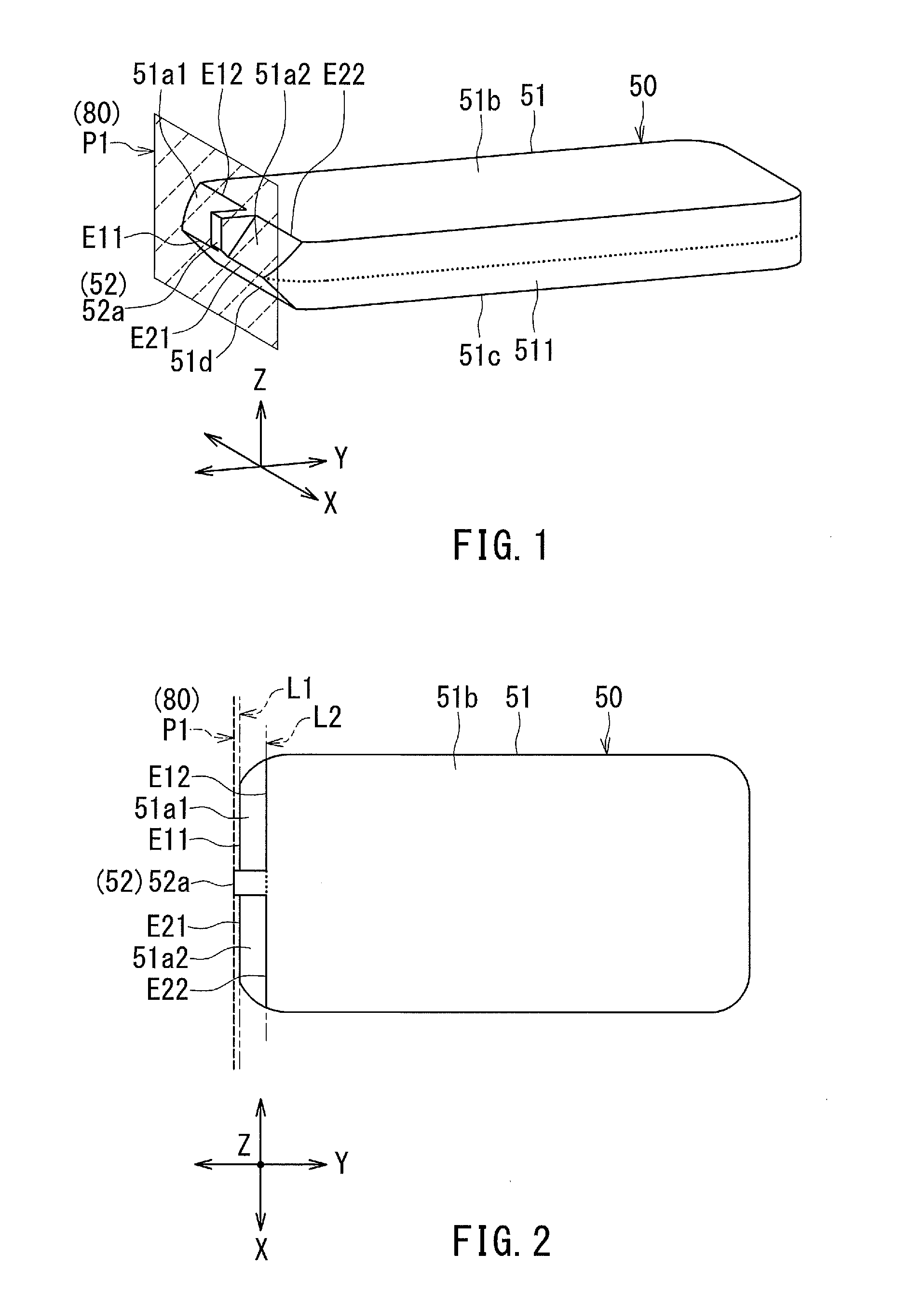
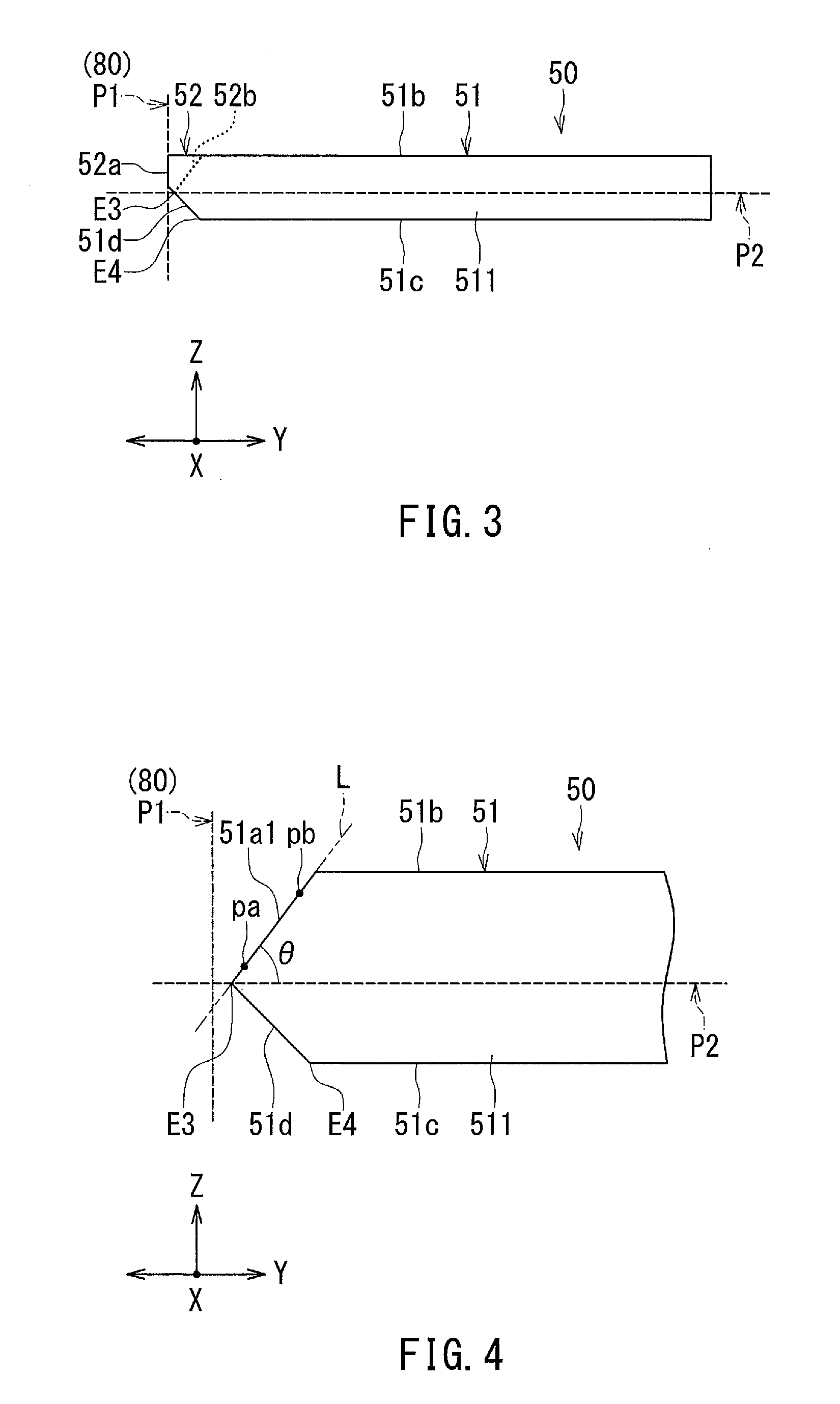
[0190]First to fourth modification examples of the plasmon generator 50 according to the present embodiment will now be described. FIG. 22 is a plan view showing the first modification example of the plasmon generator 50. In the first modification example, the top surface 51b of the main body 51 of the plasmon generator 50 is shaped differently than in FIGS. 1 and 2. More specifically, in the first modification example, the width of the top surface 51b in the track width direction (the X direction) gradually increases with increasing distance from the first imaginary plane P1 (the medium facing surface 80), and then becomes constant.

[0191]FIG. 23 is a plan view showing the second modification example of the plasmon generator 50. In the second modification example, the top surface 51b of the main body 51 of the plasmon generator 50 is shaped differently than in FIGS. 1 and 2. More specifically, in the second modification example, most part of the top surface 51b increases in width in...

second embodiment

[0198]A plasmon generator according to a second embodiment of the invention will now be described with reference to FIG. 26. FIG. 26 is a perspective view showing the plasmon generator 50 according to the present embodiment. In the present embodiment, the thickness (the dimension in the Z direction) of the plasmon generator 50 and the dimension of the near-field light generating surface 52a in the Z direction are smaller than in the first embodiment.

[0199]Reference is now made to FIG. 27 to describe how the manufacturing method for the plasmon generator 50 according to the present embodiment differs from the manufacturing method according to the first embodiment. FIG. 27 shows a stack of layers formed in the process of manufacturing a thermally-assisted magnetic recording head including the plasmon generator 50 according to the present embodiment. The components of the thermally-assisted magnetic recording head, except the plasmon generator 50, are shaped and located as in the first...


PUM


Abstract

A plasmon generator includes a main body, and a front protrusion protruding from the main body. The front protrusion has a proximal portion which is a boundary with the main body, and a near-field light generating surface located in the medium facing surface of a magnetic head. The main body has a first inclined surface and a second inclined surface each facing toward the medium facing surface. The first inclined surface and the second inclined surface are at a distance from each other and aligned in the track width direction. The proximal portion of the front protrusion is located between the first inclined surface and the second inclined surface.

Description

BACKGROUND OF THE INVENTION[0001]1. Field of the Invention[0002]The present invention relates to a thermally-assisted magnetic recording head for use in thermally-assisted magnetic recording to write data on a recording medium with the coercivity thereof lowered by irradiating the recording medium with near-field light.[0003]2. Description of the Related Art[0004]Recently, magnetic recording devices such as magnetic disk drives have been improved in recording density, and thin-film magnetic heads and recording media of improved performance have been demanded accordingly. Among the thin-film magnetic heads, a composite thin-film magnetic head has been used widely. The composite thin-film magnetic head has such a structure that a read head unit including a magnetoresistive element (hereinafter, also referred to as MR element) for reading and a write head unit including an induction-type electromagnetic transducer for writing are stacked on a substrate. In a magnetic disk drive, the th...

Claims


Application Information

Patent Timeline
IPC IPC(8): G11B11/00G11B5/012G11B7/22G11B7/1387G11B5/60G11B11/105G11B5/31G11B5/00
CPCG11B7/1387G11B7/22G11B5/012G11B2005/0021G11B5/314G11B11/10532G11B11/10543G11B5/6088G11B5/187G11B5/3116
Inventor SASAKI, YOSHITAKAITO, HIROYUKITANEMURA, SHIGEKIMAMIYA, HIDEOARAKI, HIRONORITOMITA, SEIICHIRO
Owner HEADWAY TECH INC
Why Eureka
Try Eureka