Mortar retention system for automated weapons

Active Publication Date: 2016-10-18
UNITED STATES OF AMERICA THE AS REPRESENTED BY THE SEC OF THE ARMY
View PDF6 Cites 1 Cited by
  • Summary
  • Abstract
  • Description
  • Claims
  • Application Information

AI Technical Summary

Benefits of technology

The present invention is a new retention system for a round of ammunition in a rotating continuous belt-type magazine. This system allows the round to be securely held while still being easily released for firing. The system includes cylindrical doors that are attached to a pivot shaft and can be closed with a spring to secure the round during transportation and prevent vibration. The system also includes a clamping spring that can detect the presence of the ammunition and prevent it from moving during firing loads. The system is designed to protect the critical areas of the round while still allowing it to be readily released.

Problems solved by technology

One of the challenges of automating mortar weapons is the design of a system that handles and protects the ammunition.
The standard mortar round is typically difficult to restrain securely within a magazine or ammunition feeding mechanism of an automated weapon.
In addition, the mortar round includes delicate features, such as the aluminum fins and propellant charge increments, which must be protected from damage resulting from handling and transportation.
To further exacerbate the concerns associated with traditional automated weapons, the ogive geometric shape and design of the mortar round does not provide a useful feature for securing the mortar within the ammunition feeding mechanism.
The use of a retention device against the tapered section of the mortar body is prone to wedging and jamming.
Maintaining sufficient friction to retain the round when subjected to transportation and firing loads has proven to be relatively difficult.

Method used


Image

  • Mortar retention system for automated weapons
  • Mortar retention system for automated weapons
  • Mortar retention system for automated weapons

Examples


Embodiment Construction

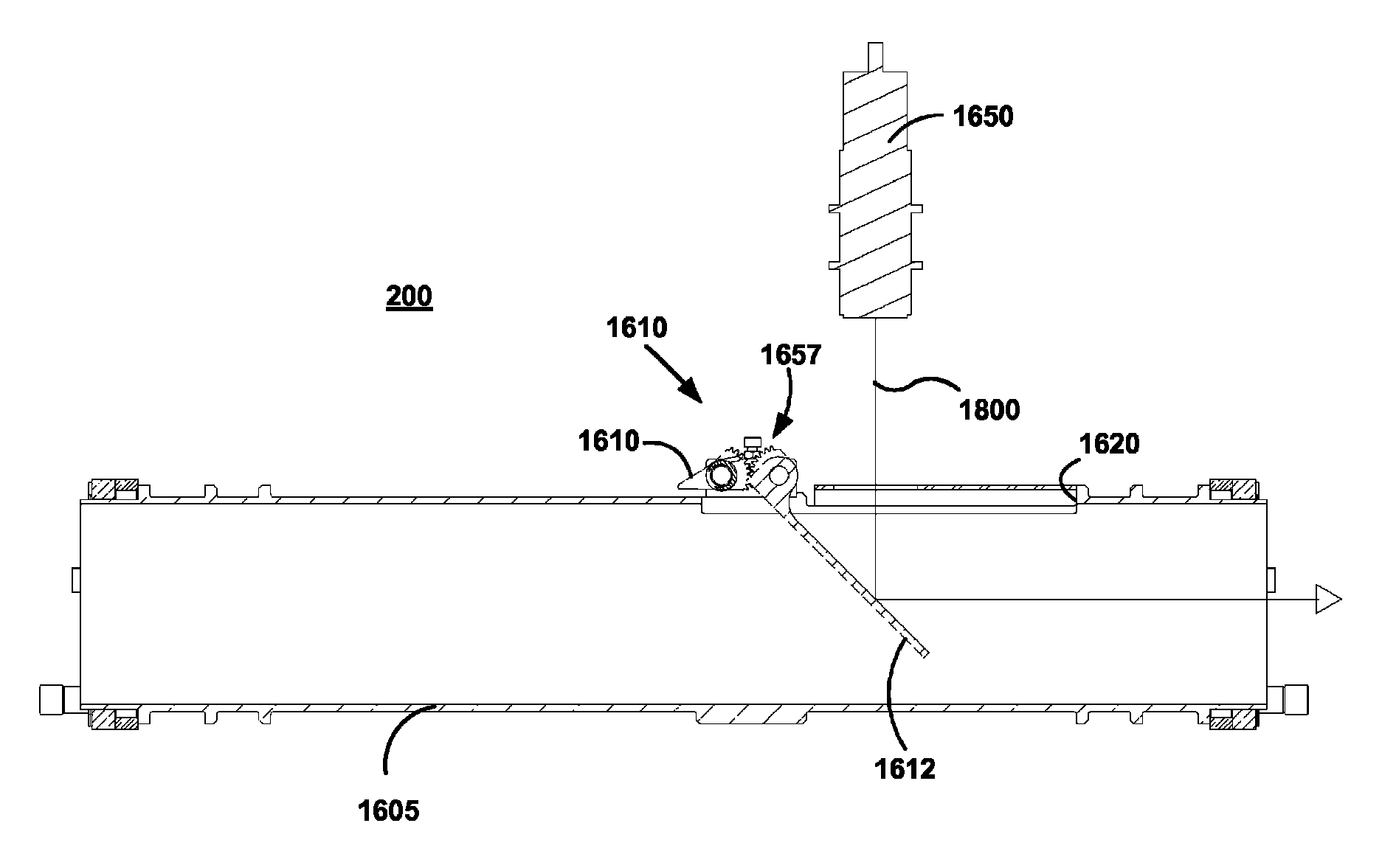
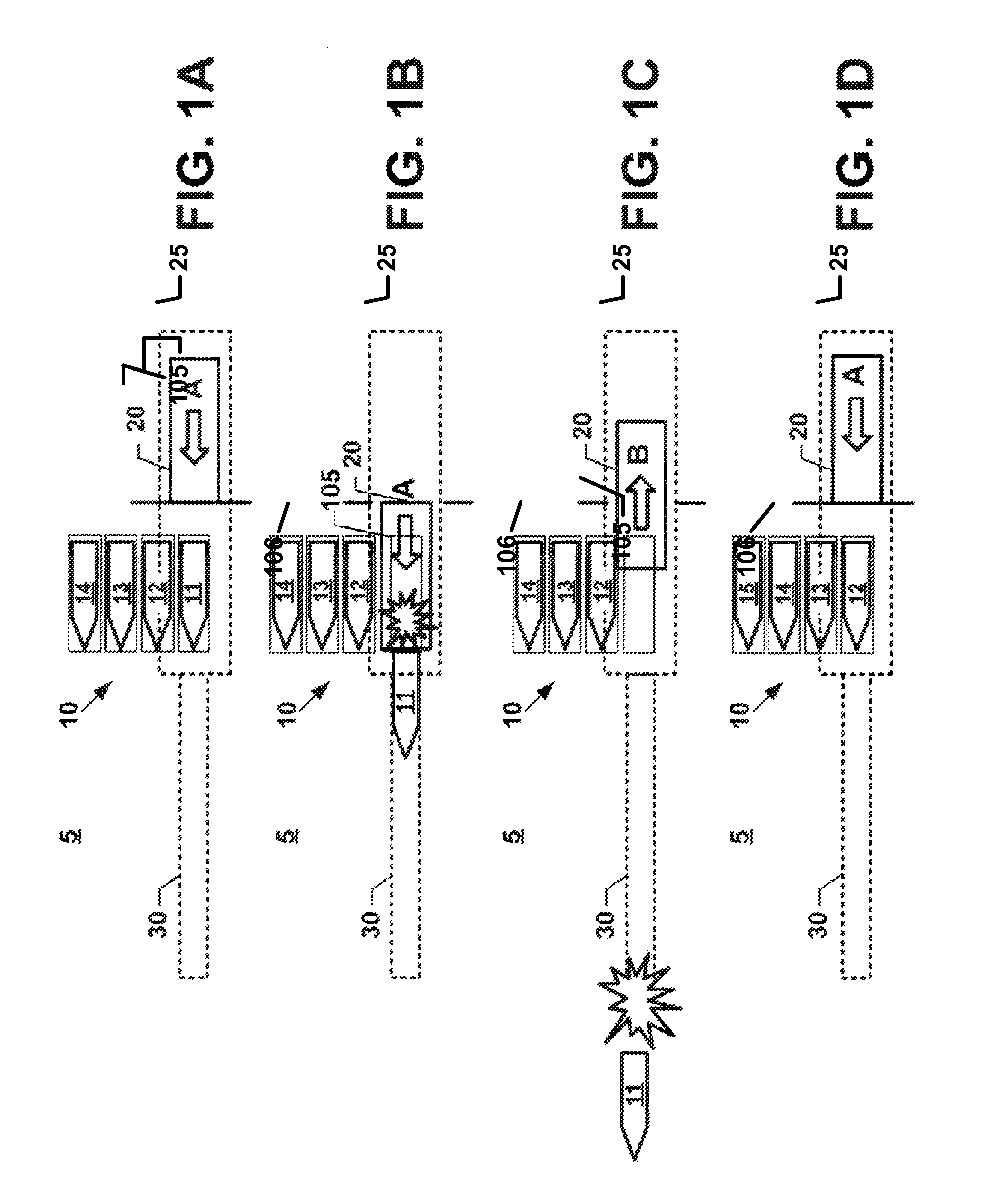
[0037]With reference to FIG. 1, it illustrates an exemplary operation of an automated weapon 5 that is provided with an ammunition feeding mechanism 10, according to a preferred embodiment of the present invention. In this example, the automated weapon 5 includes a gun tube 30, and a recoiling mass 20 that translates back and forth within a firing chamber 25. As used herein, the term “recoiling mass” generally refers to the components of the automated weapon 5 that move in response to the energy of expending an round by the automated weapon 5. This term may encompass, for example, a breech or a ramming mechanism, recoil cylinders, recoil springs or firing mechanism.

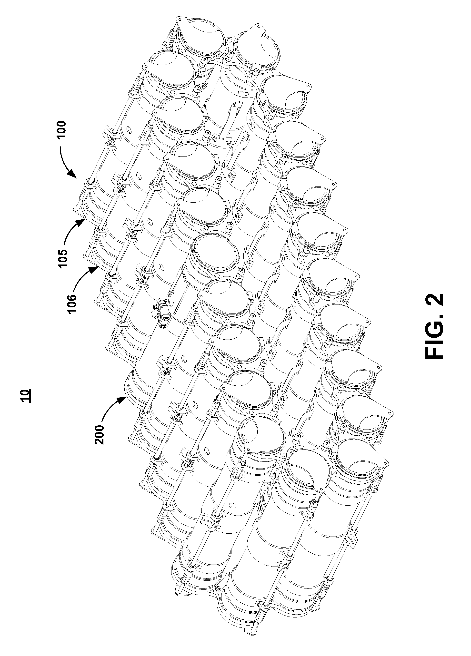
[0038]While the ammunition feeding mechanism 10 is shown as including four rounds 11, 12, 13, and 14, it should be clear that the ammunition feeding mechanism 10 can be provided with a different number of rounds, wherein each round, i.e., 11, 12, is respectively stored in a storage cell, i.e., 105, 106 (FIG. 2).

[0039]As f...


PUM


Abstract

A retention system protects the round stored inside a rotating continuous belt-type magazine, and holds the round securely while allowing it to be readily and easily released prior to firing. The retention system permits all the retaining devices to be easily retracted so that a ramming mechanism of the weapon can push the round into the chamber without interference. The gun tube of the automated weapon houses the round and provides interfaces for all other components to attach. The tube length minimizes the axial movement of the round. The round is held within the tube by a front door assembly and a rear door assembly. The door assembly is made of a crescent-shaped door attached to a pivot shaft, in order to minimize the amount of rotational travel required to open the door for loading or firing the round.

Description

GOVERNMENTAL INTEREST[0001]The invention described herein may be manufactured and used by, or for the Government of the United States for governmental purposes without the payment of any royalties thereon.FIELD OF THE INVENTION[0002]The present invention relates in general to the field of munitions. More specifically, this invention relates to a system and associated method for retaining, securing, and protecting the ammunition within a magazine or within an ammunition feeding mechanism of an automated weapon.BACKGROUND OF THE INVENTION[0003]One of the challenges of automating mortar weapons is the design of a system that handles and protects the ammunition. The standard mortar round is typically difficult to restrain securely within a magazine or ammunition feeding mechanism of an automated weapon. The round must be protected from gunfire shock, adverse weather conditions and transportation loads, while remaining ready to be fired without any user handling or intervention.[0004]In ...

Claims


Application Information

Patent Timeline
IPC IPC(8): F41F1/06F41A9/53F41A7/06F41A17/18
CPCF41A9/53F41F1/06F41A7/06F41A17/18F41A9/30F41A31/02
Inventor GORDON, NOAHTIGHE, THOMASBARTELL, WILLIAMTOMIK, MATTHEW
Owner UNITED STATES OF AMERICA THE AS REPRESENTED BY THE SEC OF THE ARMY
Why Eureka
Try Eureka