
Guiding device for guiding a despenser to draw solution from at least one well on a microplate

a technology of guiding device and dispenser, which is applied in the direction of pipe-joints, instruments, laboratory glassware, etc., can solve the problems of affecting the accuracy of the test, the solution may not be drawn in a particular angle, and the test cannot be completed quickly and accurately without an expensive automation testing system. , to achieve the effect of enhancing the convenience of the testing process, easy and low-cost, and quick results

Active Publication Date: 2016-10-11
WISTRON CORP
View PDF8 Cites 10 Cited by
  • Summary
  • Abstract
  • Description
  • Claims
  • Application Information

AI Technical Summary

Benefits of technology

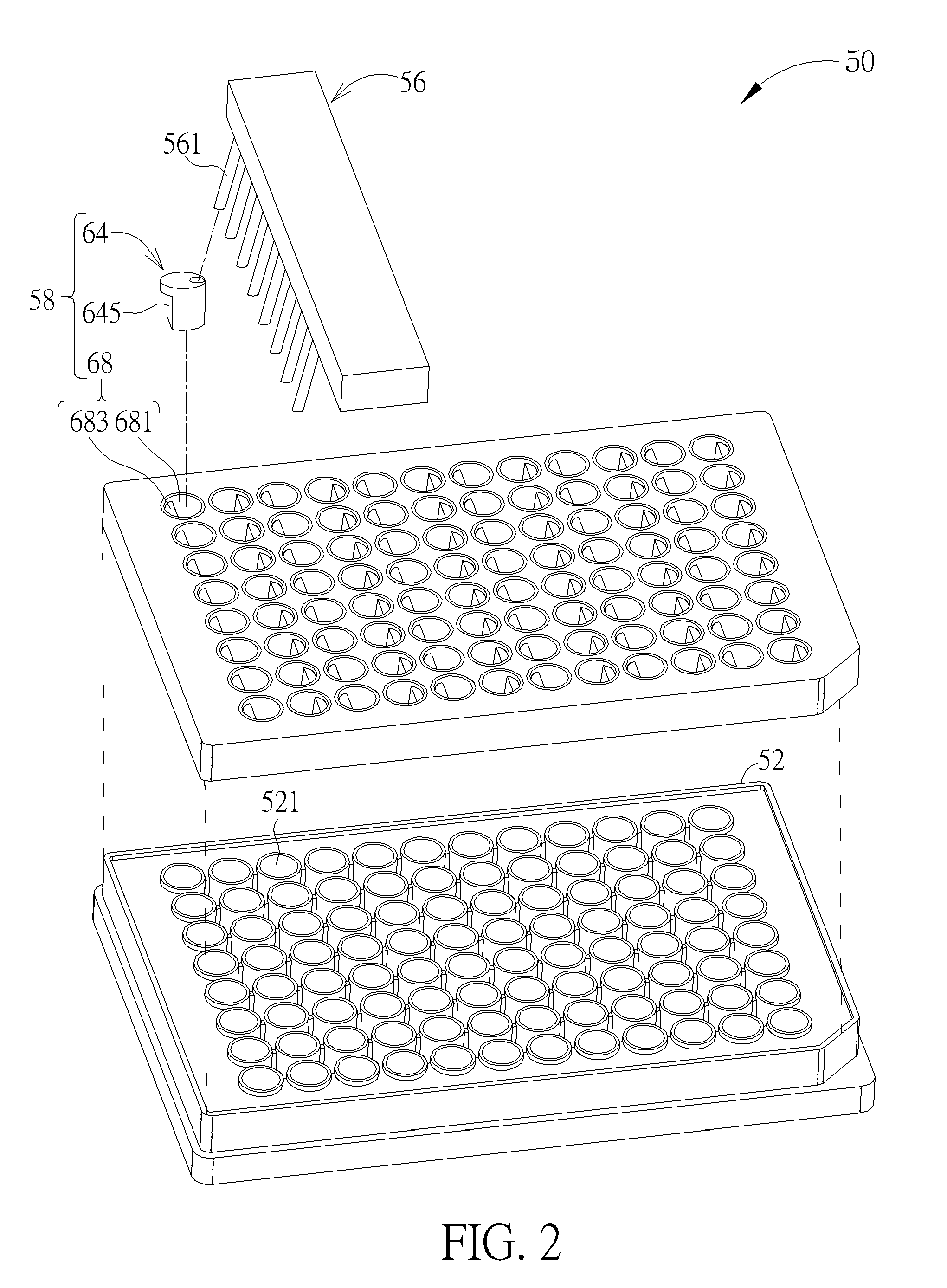
The disclosure is about a testing system that includes a microplate with wells for holding solution and magnetic specimens, a magnetic component for attracting the magnetic specimens, a dispenser for drawing solution from the wells, and a guiding device for accurately and easily guiding the dispenser's pipe to draw solution from the wells without drawing the magnetic specimens. The guiding device is easy to install and can be used to test the whole microplate or distributed magnetic specimens quickly and accurately, improving the testing process's convenience.

Problems solved by technology

However, as putting a pipe of the dispenser in a wrong place, it is easy to draw a specimen and the solution at the same time, resulting in affecting an accuracy of the test.
However, the solution may not be drawn in a particular angle without drawing the specimen at the same time in a rapid, accurate, easy and low-cost manner.
More especially, as there is a huge number of the magnetic specimens to be assayed rapidly and accurately, or as the magnetic specimens disposed in different positions and in different wells on the same microplate have to be assayed, the tests can not be finished rapidly and accurately without an expensive automation testing system.
However, in a small laboratory or when lack of funds, it relies on the experience and the physical strength of the experimenters to finish the tests, resulting in inconvenience of the testing process.

Method used


Image

  • Guiding device for guiding a despenser to draw solution from at least one well on a microplate
  • Guiding device for guiding a despenser to draw solution from at least one well on a microplate
  • Guiding device for guiding a despenser to draw solution from at least one well on a microplate

Examples


Embodiment Construction

[0025]Please refer to FIG. 1 to FIG. 3. FIG. 1 is a schematic diagram of a testing system 50 according to an embodiment of the present invention. FIG. 2 is an exploded diagram of the testing system 50 according to the embodiment of the present invention. FIG. 3 is a cross-sectional diagram of the testing system 50 according to the embodiment of the present invention. The testing system 50 includes a microplate 52, at least one magnetic component 52, a dispenser 56 and a guiding device 58. A plurality of wells 521 is formed on the microplate 52 for containing solution 60 and magnetic specimens 62. The magnetic component 54 is disposed on a side of the microplate 52 for attracting the magnetic specimens 62 contained in each of the plurality of wells 521, and the magnetic component 54 can be a magnet.

[0026]For example, please refer to FIG. 4 and FIG. 5. FIG. 4 and FIG. 5 are diagrams illustrating relative positions of the magnetic component 54 and the plurality of wells 521 according t...


PUM

PropertyMeasurementUnit
magneticaaaaaaaaaa
timeaaaaaaaaaa
physical strengthaaaaaaaaaa

Abstract

The present invention discloses a guiding device for guiding a dispenser to draw solution from at least one well on a microplate. The guiding device includes a column body whereon a first opening and a second opening are formed on opposite sides, and a slotting structure passing through the column body and communicating with the first opening and the second opening. A pipe of the dispenser passes through the first opening, the slotting structure and the second opening to reach inside the at least one well on the microplate for drawing the solution contained in the at least one well.

Description

BACKGROUND OF THE INVENTION[0001]1. Field of the Invention[0002]The present invention is to provide a guiding device, and more specifically, to a guiding device for guiding a dispenser to draw solution from at least one well on a microplate.[0003]2. Description of the Prior Art[0004]It is general to use a dispenser to draw solution from a well on a microplate for an experiment or a test. However, as putting a pipe of the dispenser in a wrong place, it is easy to draw a specimen and the solution at the same time, resulting in affecting an accuracy of the test. For example, when applying a magnetic specimen which the specimen is attracted with iron powder as a carrier, a magnet is often disposed on a lower side of the microplate to attract the magnetic specimen, and then the dispenser can be operated to draw the solution with an automation testing system or an experimenter by visual inspection. However, the solution may not be drawn in a particular angle without drawing the specimen a...

Claims


Application Information

Patent Timeline
Patent Type & Authority Patents(United States)
IPC IPC(8): G01N35/10F16L25/10B01L3/00B01L3/02
CPCF16L25/10B01L3/50853G01N35/1011B01L3/021B01L2200/025B01L2200/026B01L2300/046B01L2300/0829G01N35/1065
Inventor CHIANG, CHI-CHANLIU, TING-WENLIN, CHIH-KUANCHANG, YA-HSIN
Owner WISTRON CORP
Learn More