
Device for fixing joint structure

a technology for fixing devices and joints, applied in the direction of mechanical control devices, instruments, surgical forceps, etc., can solve the problems of insufficiently firm fixing of devices, components, constructions or the like, and achieve the effect of effective fixing of the joint structure and good fixing performan

Active Publication Date: 2016-10-11
MOVASU
View PDF11 Cites 811 Cited by
  • Summary
  • Abstract
  • Description
  • Claims
  • Application Information

AI Technical Summary

Benefits of technology

The invention provides a new joint structure fixing apparatus that has excellent fixing performance. This apparatus can effectively fix a joint structure without relying on surface friction.

Problems solved by technology

However, such devices, components, constructions or the like have often been inadequate to efficiently achieve sufficiently firm fixation.

Method used


Image

  • Device for fixing joint structure
  • Device for fixing joint structure
  • Device for fixing joint structure

Examples


Embodiment Construction

[0016]In the following detailed description of the present invention, references are made to the accompanying drawings that show, by way of illustration, specific embodiments in which the invention may be practiced. These embodiments are described in sufficient detail to enable those skilled in the art to practice the invention. It is to be understood that the various embodiments of the invention, although different from each other, are not necessarily mutually exclusive. For example, specific shapes, structures and characteristics described herein may be implemented as modified from one embodiment to another without departing from the spirit and scope of the invention. Furthermore, it shall be understood that the locations or arrangements of individual elements within each embodiment may also be modified without departing from the spirit and scope of the invention. Therefore, the following detailed description is not to be taken in a limiting sense, and the scope of the invention i...


PUM


Abstract

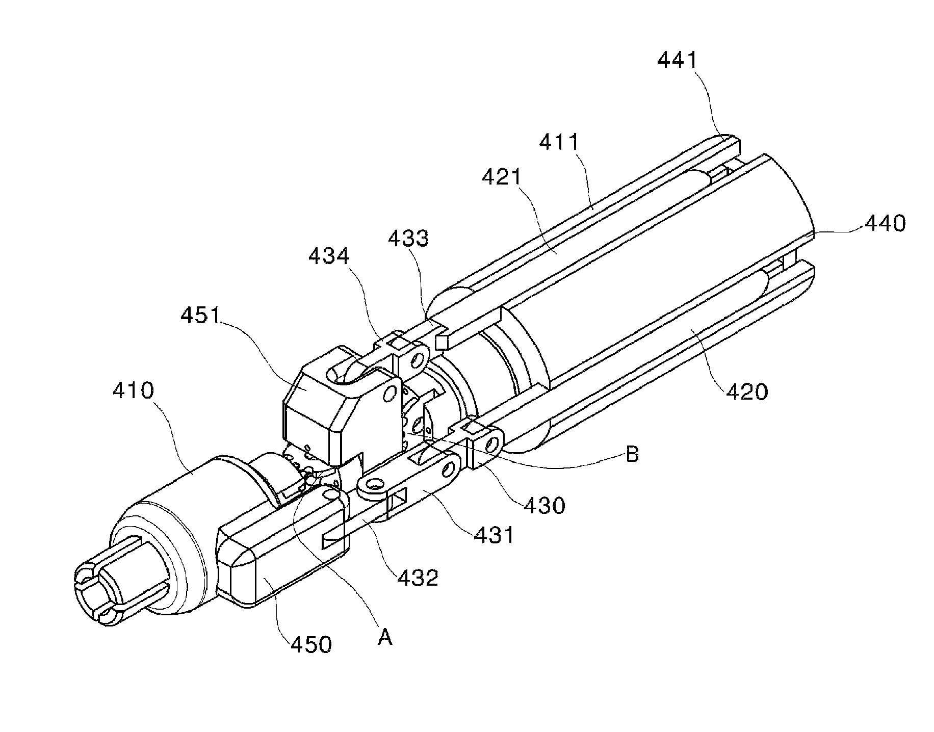
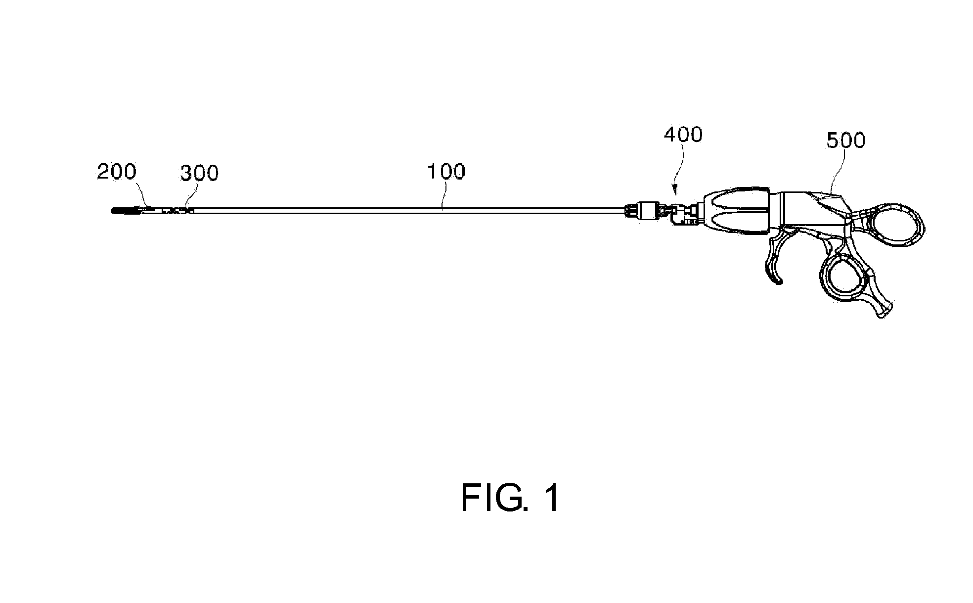
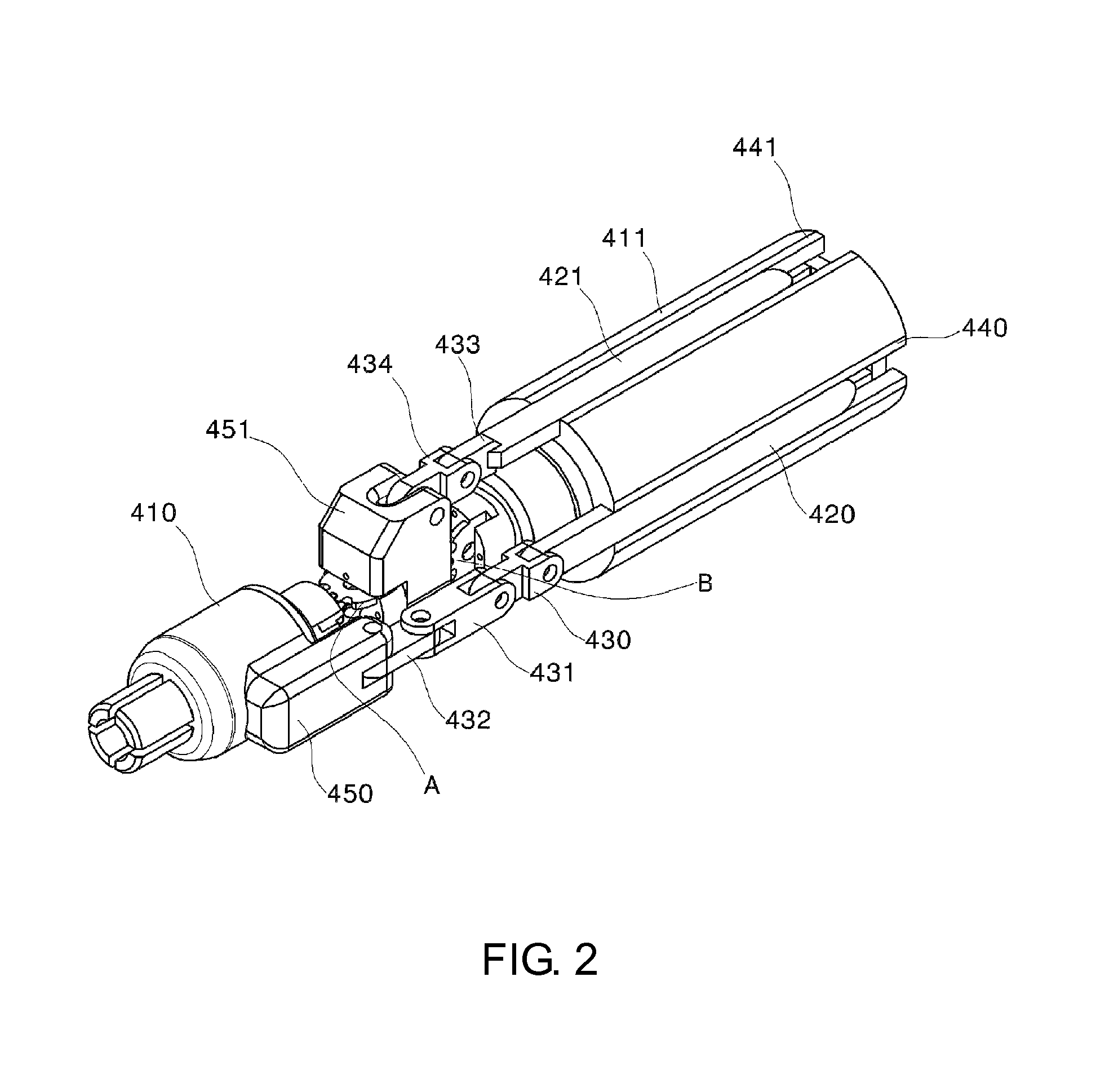
The present invention relates to a device for fixing a joint structure. The device for fixing a joint structure, according to one aspect of the present invention, comprises: a first slider for fixing a first directional joint movement state of a joint structure that includes a first joint element and a second joint element; a first locking member included in the first slider; and a first corresponding locking member which operates relative to the first locking member and blocks a forward directional movement and a backward directional movement of the first slider.

Description

FIELD OF THE INVENTION[0001]The present invention relates to an apparatus for fixing a joint structure.BACKGROUND[0002]Joint motion may refer to the movement of at least one of two or more interconnected (mechanical) elements relative to the other ones. Such joint motion may be observed in various forms from human arms or legs to robotic arms of an industrial robot.[0003]In some cases, instruments (particularly surgical instruments) capable of joint motion are required to fix the joint motion state of the mechanical elements thereof. In order to fix the joint structure, there have been conventionally used devices or components configured with balls and sockets, which mainly rely upon the surface friction between two mechanical elements, as disclosed in Korean Patent Application No. 2011-3192 of the applicant(s) (the contents of which are to be regarded as being incorporated herein by reference in its entirety); a construction for fixing the motion state of a joint by fixing only wir...

Claims


Application Information

Patent Timeline
Patent Type & Authority Patents(United States)
IPC IPC(8): G05G5/02A61B17/29A61B17/00
CPCA61B17/29A61B90/14G05G5/02A61B2017/003A61B2017/2927Y10T74/20636A61B2034/305A61B2090/508A61B34/70A61B17/00B25J17/00
Inventor JEONG, CHANG WOOKKIM, HYUNG TAE
Owner MOVASU
Learn More