
Assembly for blocking cooling water channel in mold

a technology of cooling water channel and mold, which is applied in the direction of mechanical equipment, pipes/joints/fittings, pipe elements, etc., can solve the problems of difficult to completely stop the cooling water flowing through the channel, and achieve the effect of reducing the number of molds

Inactive Publication Date: 2016-10-04
JANG YOUNG HYUN
View PDF16 Cites 0 Cited by
  • Summary
  • Abstract
  • Description
  • Claims
  • Application Information

AI Technical Summary

Benefits of technology

[0017]Accordingly, the present invention has been made keeping in mind the above problems occurring in the related art, and the present invention is intended to propose an assembly for blocking a cooling water channel in a mold, which can hermetically block a cooling water channel to be blocked in a mold, has durability sufficient to resist deformation or damage due to the repeated heating and cooling for the features of a mold, and can be manufactured at a low cost with a minimum configuration and low weight.
[0020]According to the assembly for blocking a cooling water channel in a mold, it is possible to hermetically block a cooling water channel to be blocked in a mold, to achieve durability sufficient against deformation or damage due to the repeated heating and cooling for the features of a mold, and to manufacture the assembly at a low cost with a minimum configuration and low weight.

Problems solved by technology

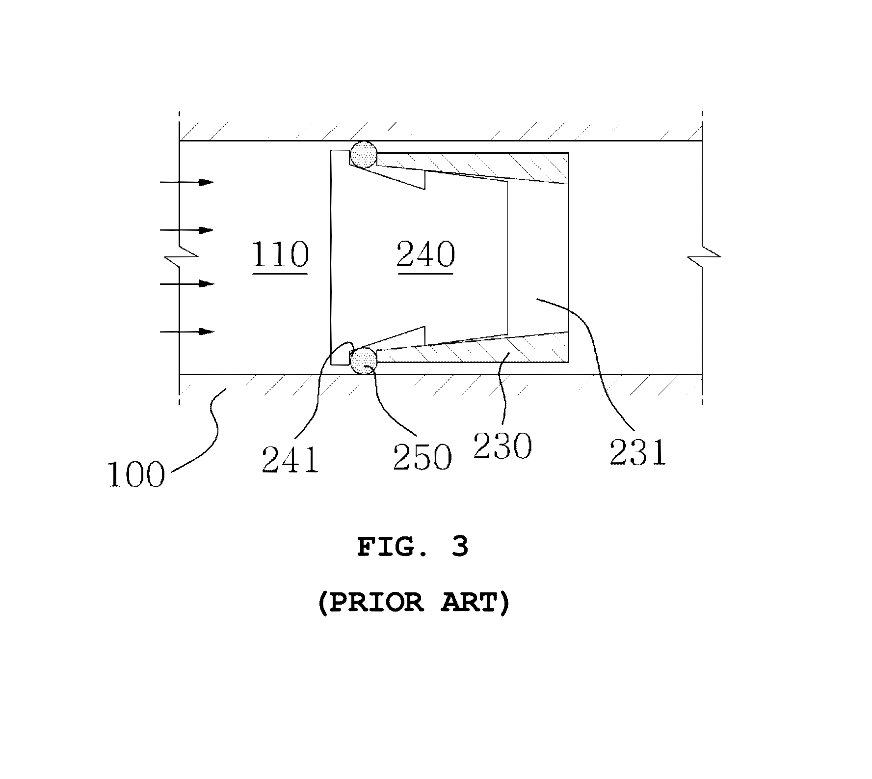
However, the assembly 200 for blocking a cooling water channel having this configuration has a problem in that it is difficult to completely stop cooling water flowing through the channel under high pressure, because sealing forces between the outer side of the first member 210 and the channel 110 and between the inner side of the first member 210 and the blocking member 220 are not sufficient.

Method used


Image

  • Assembly for blocking cooling water channel in mold
  • Assembly for blocking cooling water channel in mold
  • Assembly for blocking cooling water channel in mold

Examples


Embodiment Construction

[0030]Embodiments of an assembly for blocking a cooling water channel in a mold according to the present invention will be described in detail hereafter with reference to the accompanying drawings.

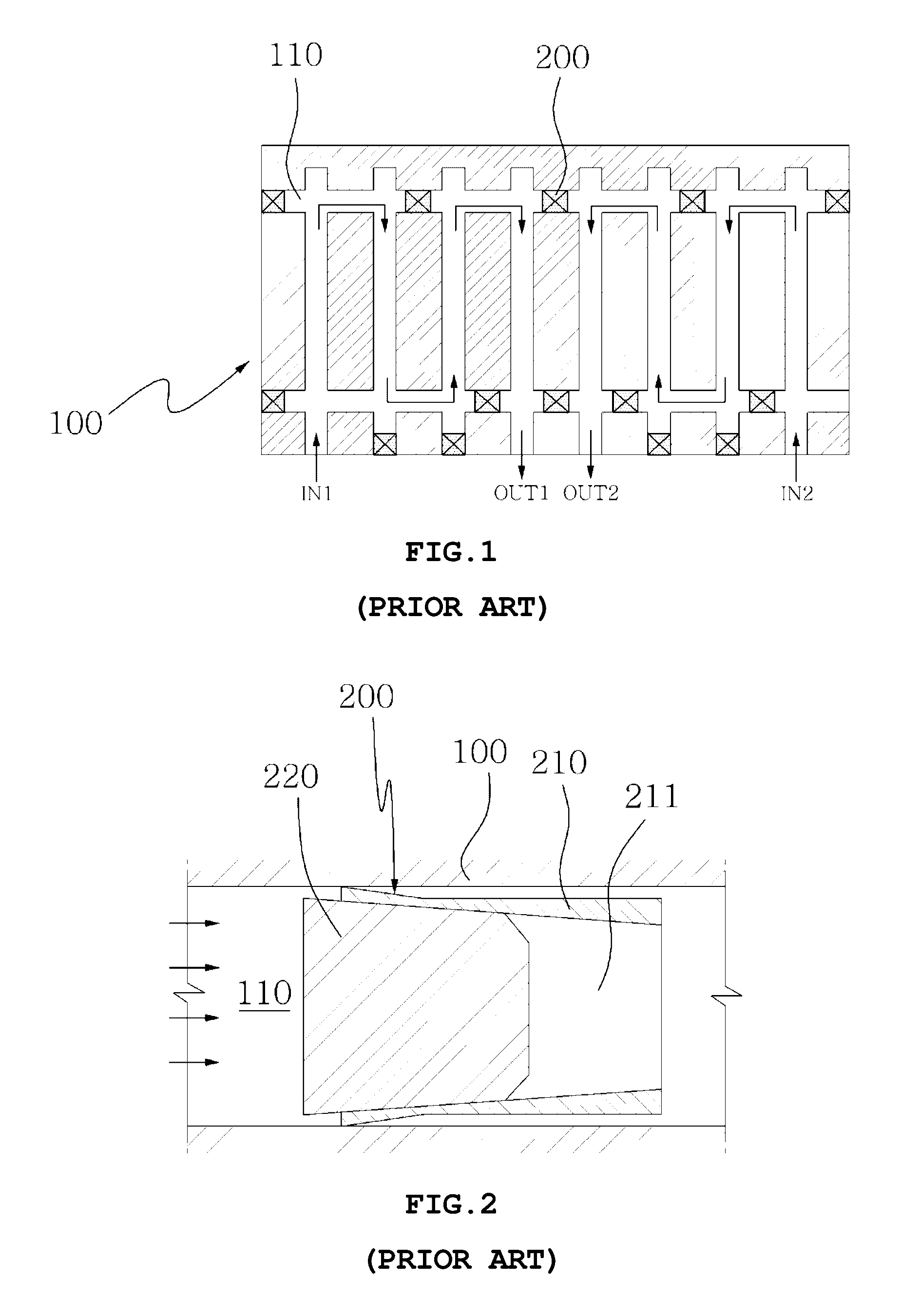
[0031]An assembly for blocking a cooling water channel in a mold according to the present invention can be manufactured at a low cost with chemical resistance, thermal resistance, durability, low weight, and a simple configuration, in addition to hermetically blocking a cooling water channel to stop the flow of cooling water in order to switch a cooling water channel in a mold, as shown in FIG. 1.

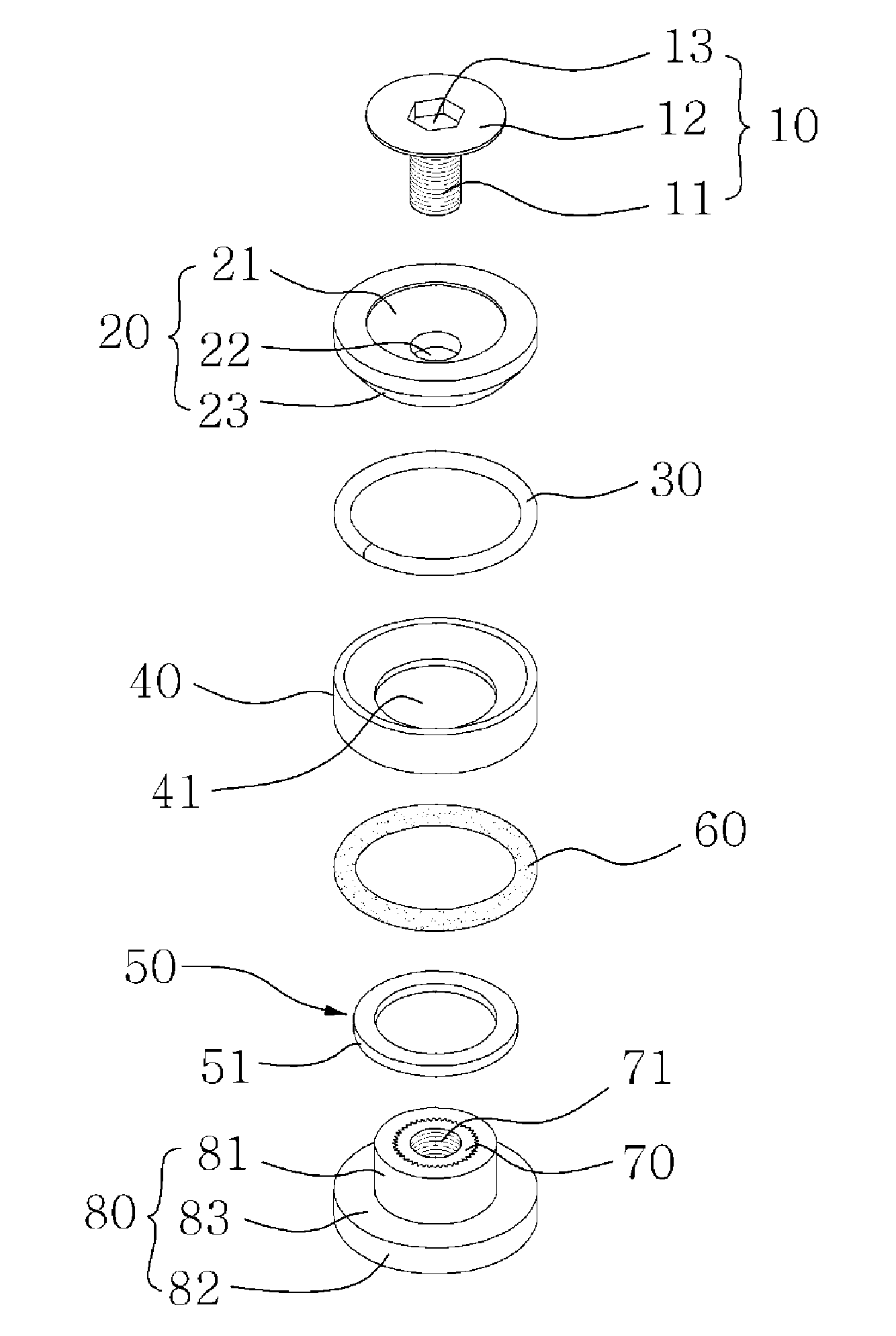
[0032]The basic configuration of the assembly, as shown in FIGS. 4 to 6, includes a bolt 10 with a threaded-shank 11 and a head 12, a base 70 with a threaded-hole 71 for thread-fastening the thread-shank, and an elastic ring 60, an elastic ring-fixing member 50, a pressing ring 40, an expansion ring 30, and a seat member 20 which are disposed between the bolt and the base.

[0033]In the configuratio...


PUM

PropertyMeasurementUnit
outer diameteraaaaaaaaaa
groove shapeaaaaaaaaaa
arc extension shapeaaaaaaaaaa

Abstract

The present invention relates to an assembly for blocking a cooling water channel in a mold, which includes a bolt with a threaded-shank and a head, a base with a threaded-hole for thread-fastening the thread-shank, and an elastic ring, an elastic ring-fixing member, a pressing ring, an expansion ring, and a seat member which are disposed between the bolt and the base from the base to the bolt. The elastic ring-fixing member has an elastic ring seat holding the inner side of the elastic ring, the inner side of the elastic ring is fitted in the elastic ring seat, a body is made by insert-molding nylon to protect the base with the threaded-hole and composed of an upper cylindrical portion, a lower cylindrical portion larger in outer diameter than the upper cylindrical portion, and a step formed at the joint of the upper and lower cylindrical portions.

Description

CROSS REFERENCE TO RELATED APPLICATION(S)[0001]This application claims the benefit of Korean Patent Application No. 10-2014-101158, filed on Aug. 6, 2014, which are hereby incorporated by reference in its entirety into this application.BACKGROUND OF THE INVENTION[0002]1. Field of the Invention[0003]The present invention relates, in general, to an assembly for blocking a cooling water channel in a mold, which hermetically blocks a cooling water channel to stop the flow of cooling water, when switching a cooling water channel in a mold, and which has thermal resistance and durability.[0004]2. Description of the Related Art[0005]In general, cooling water channels are provided for allowing cooling water to flow to cool products made by molds, and in switching of channels for cooling water, as shown in FIG. 1, a channel 10 to stop flow of cooling water in a mold 100 is blocked by an assembly 200 for blocking a cooling water channel and the cooling water is guided to other desired channel...

Claims


Application Information

Patent Timeline
Patent Type & Authority Patents(United States)
IPC IPC(8): F16L55/10B29C33/04F16L55/132
CPCB29C33/04F16L55/132
Inventor JANG, YOUNG-HYUN
Owner JANG YOUNG HYUN
Learn More