
Module for determining an operating characteristic of a bearing

a technology for operating characteristics and measuring modules, applied in the field of measurement modules, can solve the problems of wasting time and expensive to individually attach the different sensor types

Active Publication Date: 2016-09-27
AB SKF
View PDF10 Cites 9 Cited by
  • Summary
  • Abstract
  • Description
  • Claims
  • Application Information

AI Technical Summary

Benefits of technology

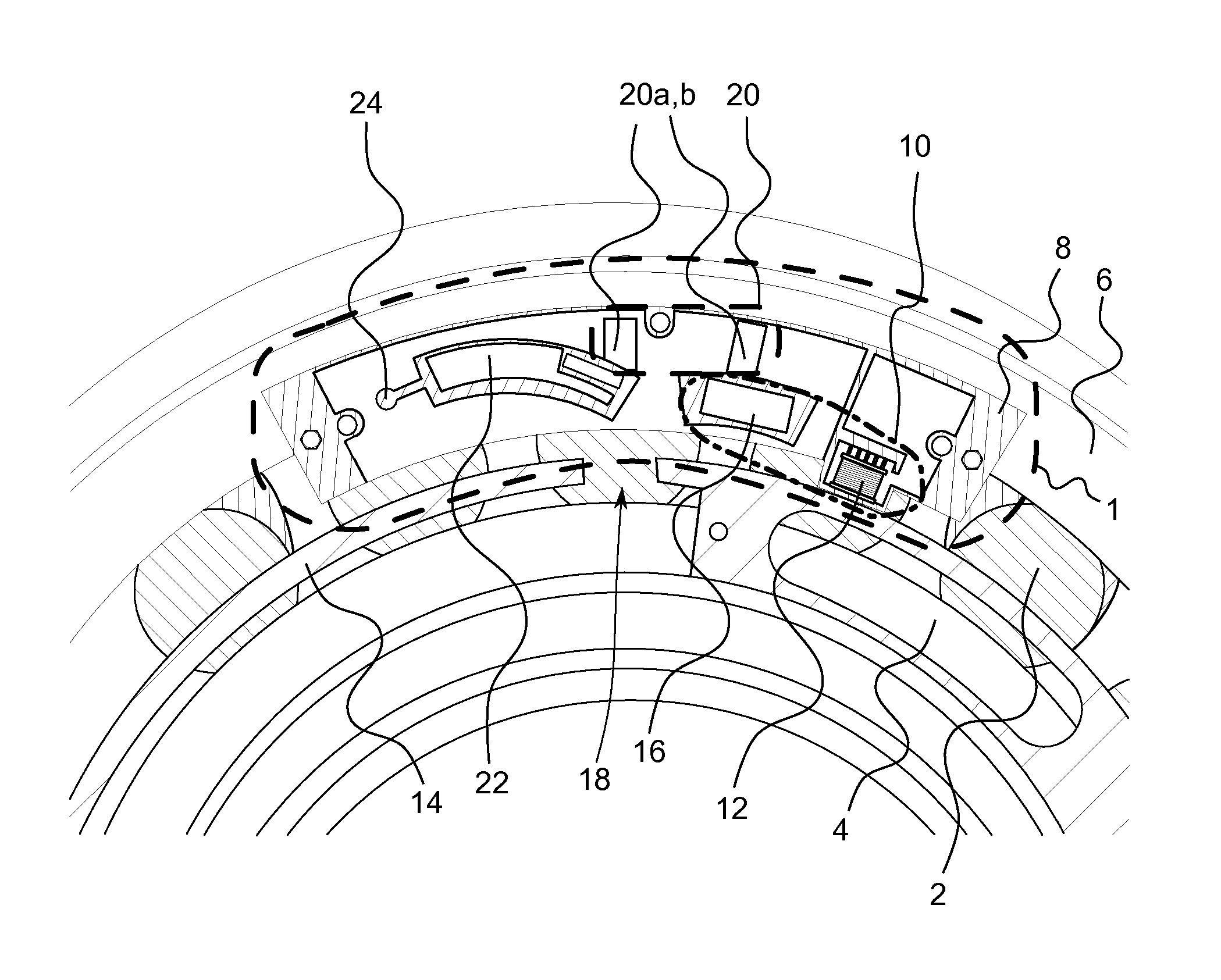
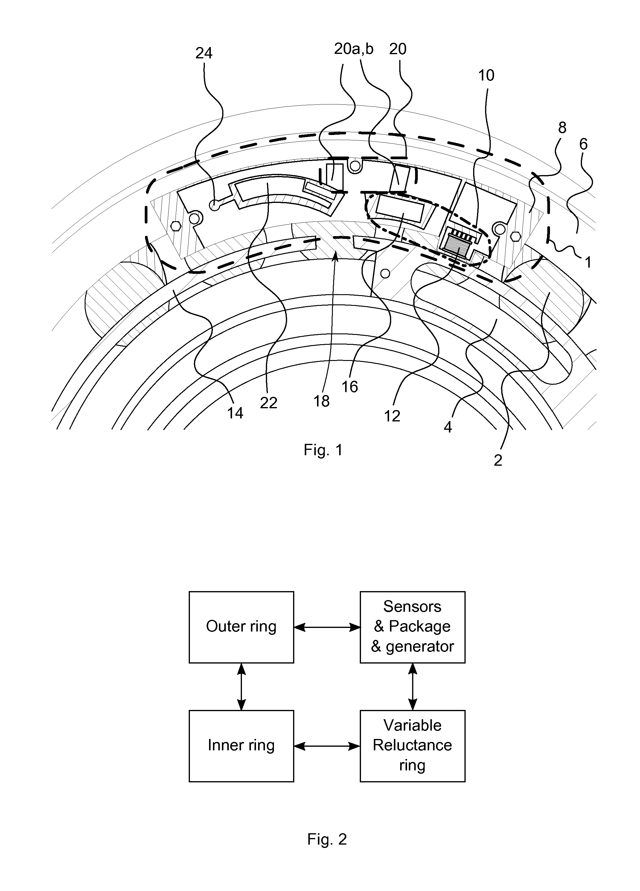
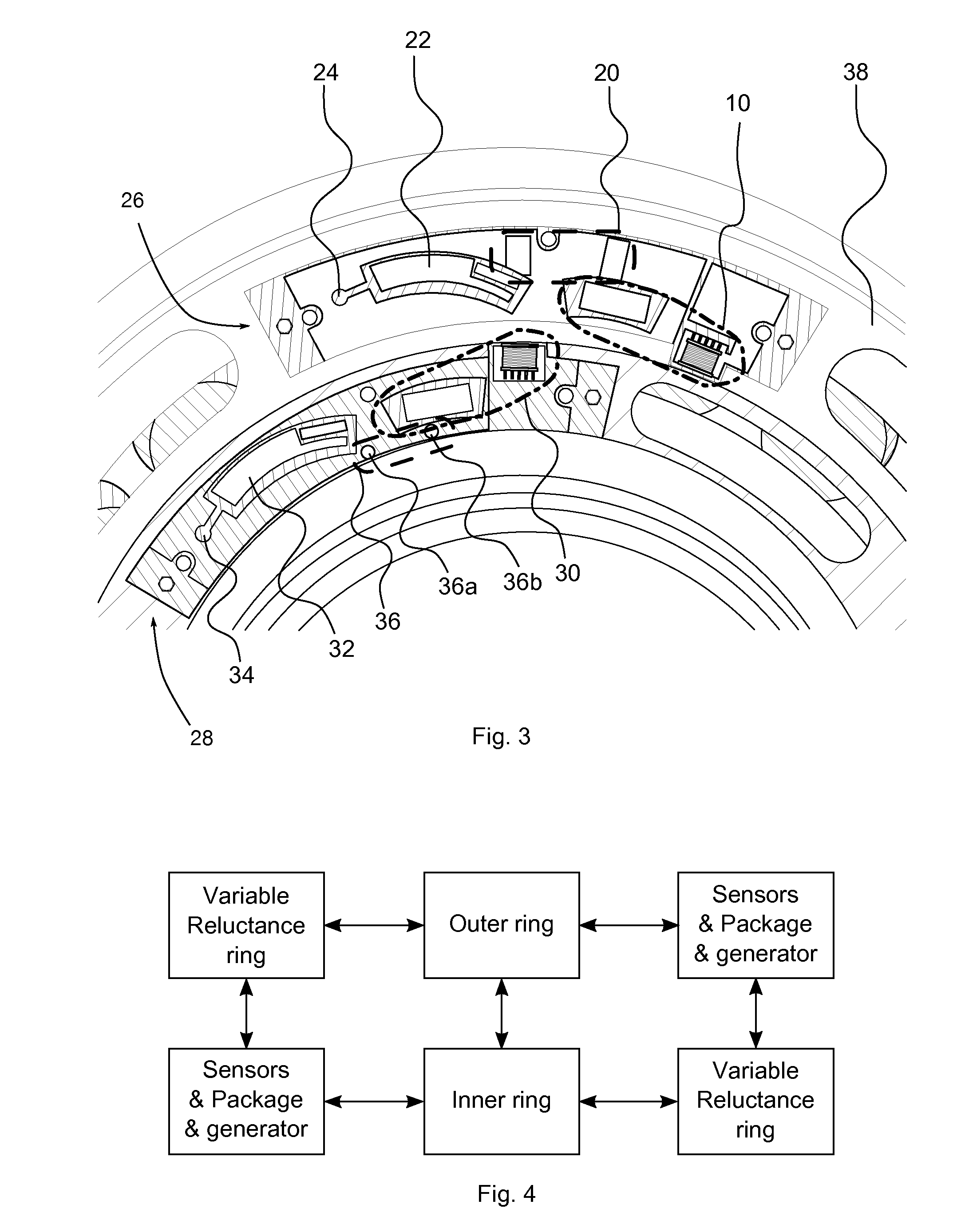
The present invention provides a measurement module for monitoring the operating condition of a roller bearing by using an energy harvesting device and a deformation sensor. The module is enclosed in a common housing that includes all components required for load monitoring, making it easy to mount on the roller bearing. The energy harvesting device can generate energy from a magnetic field without needing physical contact with the opposing bearing ring. The deformation sensor is placed on a surface region of the bearing to determine the load on the bearing with utmost precision. The common housing has a contour or border that matches the shape of the bearing ring to which the module is attached. The module comprises one or more permanent magnets that can be mounted on either bearing ring, and a wireless transmitter is coupled with the evaluation circuit for transmitting the strain signal or information on the strain signal without the need for external wiring.

Problems solved by technology

It may be rather time consuming and expensive to individually attach the different sensor types and the associated evaluation electronics and energy sources to the roller bearings.
Furthermore, conventional solutions require excessive amounts of additional space in the environment of the roller bearing so that typically completely new constructions had to be performed, when condition monitoring had to be integrated into a roller bearing.

Method used


Image

  • Module for determining an operating characteristic of a bearing
  • Module for determining an operating characteristic of a bearing
  • Module for determining an operating characteristic of a bearing

Examples


Embodiment Construction

[0031]Various embodiments will now be described with reference to the accompanying figures in which only some exemplary embodiments are illustrated. For the sake of clarity, individual components, lines, layers and / or regions within the figures may not be drawn to scale.

[0032]It should be understood, however, that there is no intent to limit further embodiments to the particular implementations disclosed in the following figures. To the contrary, it is pointed out that further embodiments may use alternative implementations or modifications and equivalents of the implementations disclosed in the figures which fall within the scope of the invention. In particular, the fact that individual functionalities are described with respect to different entities, functional blocks or devices shall not be construed to mean that those entities are physically separated in all possible further embodiments of the present invention. Further embodiments may also unite several functionalities in a sin...


PUM

PropertyMeasurementUnit
energyaaaaaaaaaa
magnetic fieldaaaaaaaaaa
sizeaaaaaaaaaa

Abstract

A measurement module for monitoring an operating condition of a roller bearing having a first bearing ring and a second bearing ring rotating with respect to each other around a rotation axis comprises an energy harvesting device operable to generate energy from a relative movement between the first and second bearing rings and at least one deformation sensor operable to provide a deformation signal indicative of a deformation of a surface region of one bearing ring of the first and the second bearing rings. The deformation sensor is powered by the energy harvesting device. An evaluation circuit is operable to determine, using the deformation signal, a strain signal indicative of a present load on the bearing. The evaluation circuit is powered by the energy harvesting device and a common housing encloses the energy harvesting device, the deformation sensor and the evaluation circuit.

Description

CROSS REFERENCE TO RELATED APPLICATIONS[0001]This is a National Stage application claiming the benefit of International Application Number PCT / EP2012 / 073529 filed on 23 Nov. 2012, which claims the benefit of U.S. Provisional Patent Application No. 61 / 637,539 filed on 24 Apr. 2012, both of which are incorporated herein by reference in their entireties.FIELD OF THE INVENTION[0002]Embodiments of the present invention relate to condition monitoring of roller bearings and in particular to a measurement module for monitoring an operating condition of a roller bearing having a first bearing ring and a second bearing ring rotating with respect to each other.BACKGROUND OF THE PRESENT INVENTION[0003]Condition monitoring of roller bearings is of increasing importance, particularly in applications with roller bearings of intermediate and greater size, such as for example the roller bearings used in wind energy converters or in other types of power plants, in general.[0004]One particular example...

Claims


Application Information

Patent Timeline
Patent Type & Authority Patents(United States)
IPC IPC(8): G01M13/04G01K13/00F16C33/58F16C19/52F16C41/00
CPCG01M13/045F16C19/522F16C19/525F16C33/58F16C33/586F16C41/00F16C41/004F16C41/008G01K13/00F16C2233/00F16C19/38F16C23/086G01B21/32G01M13/04G01N29/14G08C17/02H02N11/00Y02E10/72G16Z99/00
Inventor ERSKINE, JOSEPHHAMILTON, KEITHMURRAY, BRIANVAN DER HAM, ANDREAS CLEMENS
Owner AB SKF
Learn More