Track pad

a technology of track pad and shearing force, which is applied in the field of track pad, can solve the problems of large shearing force acting on the screws, large shearing force on the screws, and considerable wear and tear achieves the effects of improving the properties of the track pad, facilitating the rotation of the chain wheel drive, and good adhesion

Active Publication Date: 2016-09-20
LIEBHERR MINING EQUIP COLMAR
View PDF15 Cites 8 Cited by
  • Summary
  • Abstract
  • Description
  • Claims
  • Application Information

AI Technical Summary

Benefits of technology

The present invention provides a track pad for a chain of a chain wheel drive that has both grouser and flat parts on the bearing surface. This combines the benefits of a grouser pad profile and a flat pad profile, leading to improved adherence properties and better turning properties of the chain wheel drive. The grouser tapers towards the lower outer portion of the track pad, also contributing to the improved turning properties.

Problems solved by technology

However, when the machine moves around a corner, the two chain wheel drives perform a rotating movement such that the grip provided by the grousers creates large shearing forces within the chain.
In particular, when the track pads are fixed to the chain elements of the chain by fixing screws, there will be large shearing forces acting on these screws and the portion of the track pad where the screws are located.
This will lead to considerable wear-down of the track pads grousers and might lead to the shearing of the fixing screws.
Further, the grousers of known grouser pads also create a lot of destruction on the soil during rotation of the chain wheel drive around a vertical axis.

Method used


Image

  • Track pad
  • Track pad
  • Track pad

Examples


third embodiment

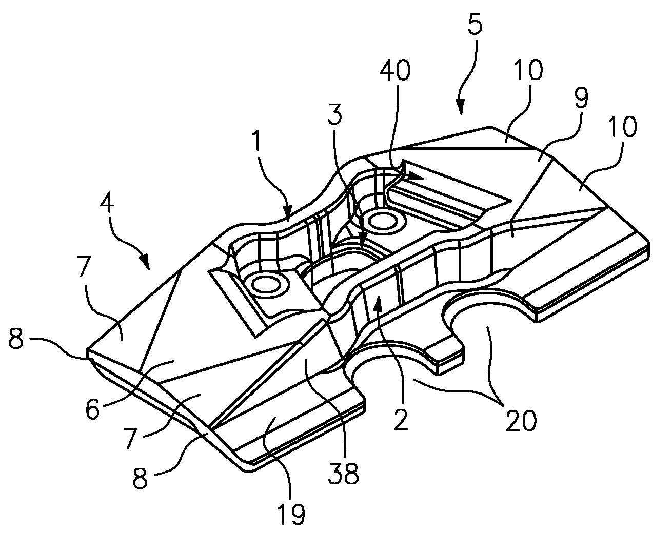
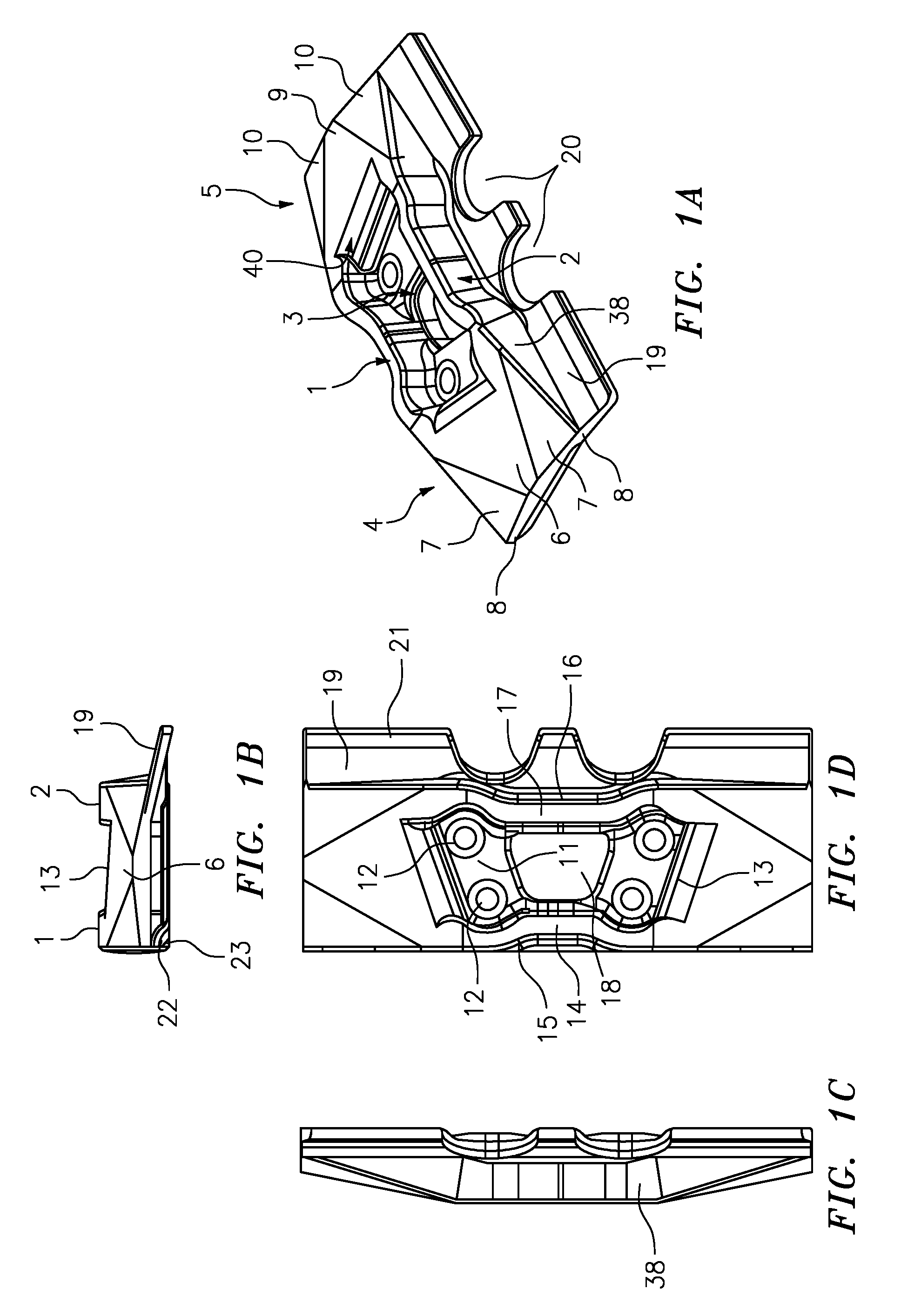
[0078]FIGS. 1 to 3 show a first, a second and a track pad according to the present invention incorporating both the first and the second aspect of the present invention.

[0079]According to the first aspect, the track pad has a bearing surface provided with grousers 1 and 2 in a central grouser part and flat lateral parts 4 and 5 on both sides of the central grouser part in the lateral direction. According to the second aspect of the present invention, the bearing surface of the base plate 40 from which the grousers 1 and 2 project has a profile in the lateral direction.

[0080]In the first and second embodiments shown in FIGS. 1 and 2, the bearing surface of the base plate 40 has the same profile as the grousers in the flat lateral parts 4 and 5, such that no distinction between the grousers and the base plate is discernable in this region.

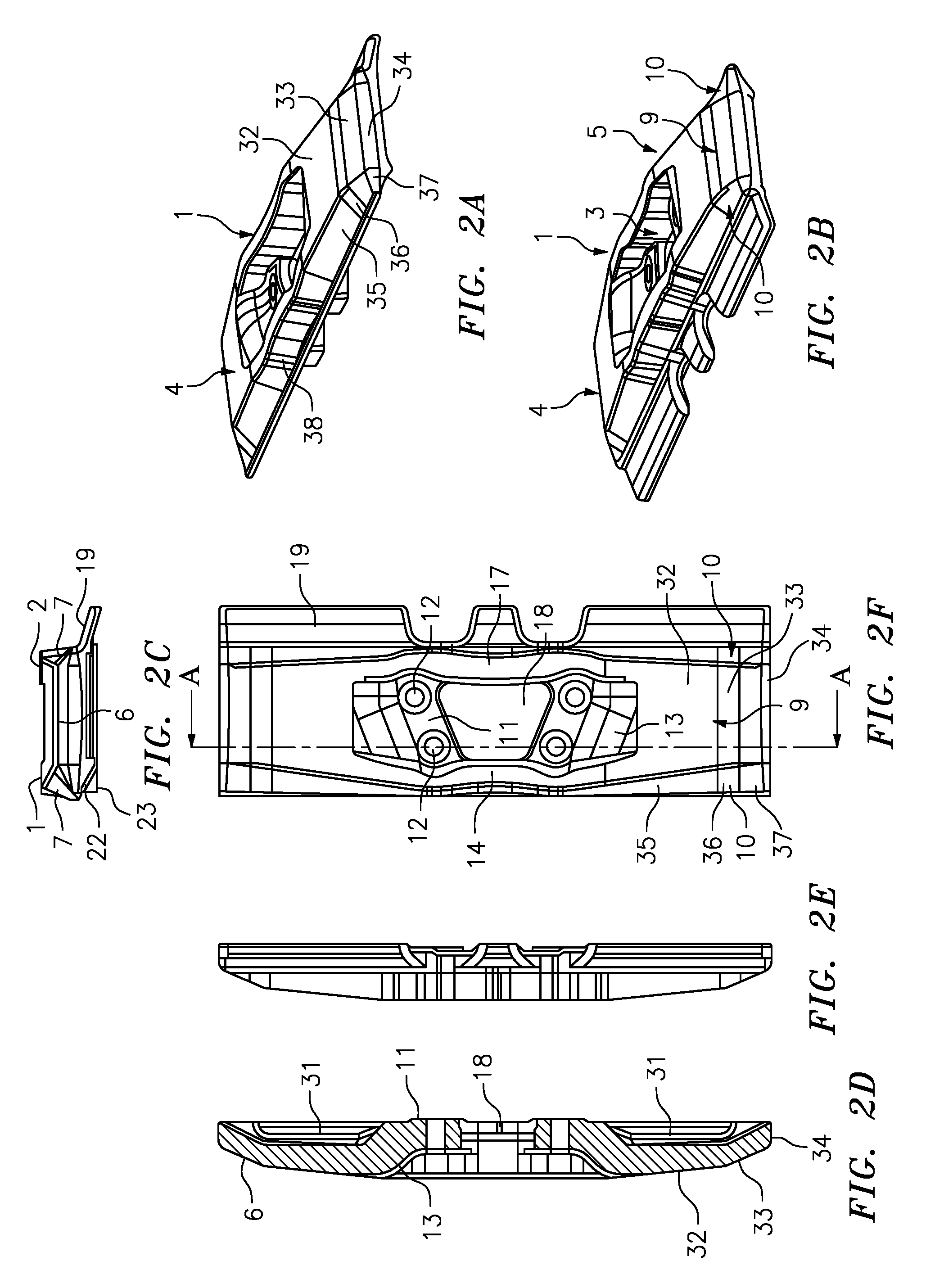
[0081]In contrast, in the third embodiment shown in FIG. 3, the grousers have lateral grouser sections 32 and 33 extending in the flat lateral regio...

first embodiment

[0086]In the first embodiment, the corner portions and the middle flat portion are each formed by single flat section having constant taper. Further, at the lateral edges, the corner portions each have an extension in the longitudinal direction that is larger than the extension of the middle flat portion in the longitudinal direction.

second embodiment

[0087]In the second embodiment, the corner portions 7 and the middle flat portion 6 have a taper that gradually increases in the lateral direction. In particular, the middle flat portion 6 is formed by a first flat section 32 having a first taper, followed by a second flat section 33 having a second, larger taper. The first and second flat sections both have approximately constant taper and are joined by a rounded section. Further, the lateral edge 34 of the middle flat portion 6 is rounded.

[0088]The corner portions 7 in the second embodiment essentially follow this form of the middle flat section 6, with a first corner flat sections35 followed by a second corner flat section 37 having a larger taper and a rounded edge corner section 37. The taper of the portions 7 increases both with respect to the lateral, as well as the longitudinal direction.

[0089]Further, in the second embodiment, at the lateral edges, the corner portions 7 each have an extension in the longitudinal direction t...


PUM


Abstract

The present invention relates to a track pad for a chain of a chain wheel drive, the track pad having a bearing surface provided with at least one grouser (1, 2), extending in the lateral direction of the bearing surface, wherein at least one flat part (4, 5) is provided next to at least one grouser part (1, 2) in the lateral direction of the bearing surface. Further, the invention comprises a track pad for a chain of a chain wheel drive, the track pad having a bearing surface provided with at least one grouser (32, 33) protruding from a base plate (40), the grouser (32, 33) extending in the lateral direction of the bearing surface, wherein the bearing surface of the base plate has a profile in the lateral direction.

Description

BACKGROUND OF THE INVENTION[0001]The present invention relates to a track pad for a chain of a chain wheel drive, the track pad having a bearing surface provided with at least one grouser extending in the lateral direction of the bearing surface. In particular, the grouser may extend form a base plate of the track pad.[0002]Known track pads have a grouser pad profile of the bearing surface in order to provide a maximum of grip of the bearing surface with the ground for translational movement in the forward or backward direction or a flat pad profile to provide a maximum contact surface of the bearing surface.[0003]In known track pads having a grouser pad profile, the track pad is constituted by a flat base plate from which the grousers extend along the entire lateral width and have, at least over most part of the track pad, the same elevation. Such a track pad may be mounted to a chain of a chain wheel drive by screws that go through holes provided in the base plate.[0004]However, w...

Claims


Application Information

Patent Timeline
IPC IPC(8): B62D55/26B62D55/06B62D55/28
CPCB62D55/06B62D55/26B62D55/28
Inventor WEI.BETA., OLIVERNEYER, FREDERICDREYER, VINCENT
Owner LIEBHERR MINING EQUIP COLMAR
Why Eureka
Try Eureka