
Current sensing multiple output current stimulators

a stimulator and current sensing technology, applied in the field of current mirror circuits, can solve problems such as long turn on times for errors regarding the amplitude of current delivered, and inability to achieve the effect of delivering small output current levels

Active Publication Date: 2016-09-20
ALFRED E MANN FOUND FOR SCI RES
View PDF300 Cites 12 Cited by
  • Summary
  • Abstract
  • Description
  • Claims
  • Application Information

AI Technical Summary

Problems solved by technology

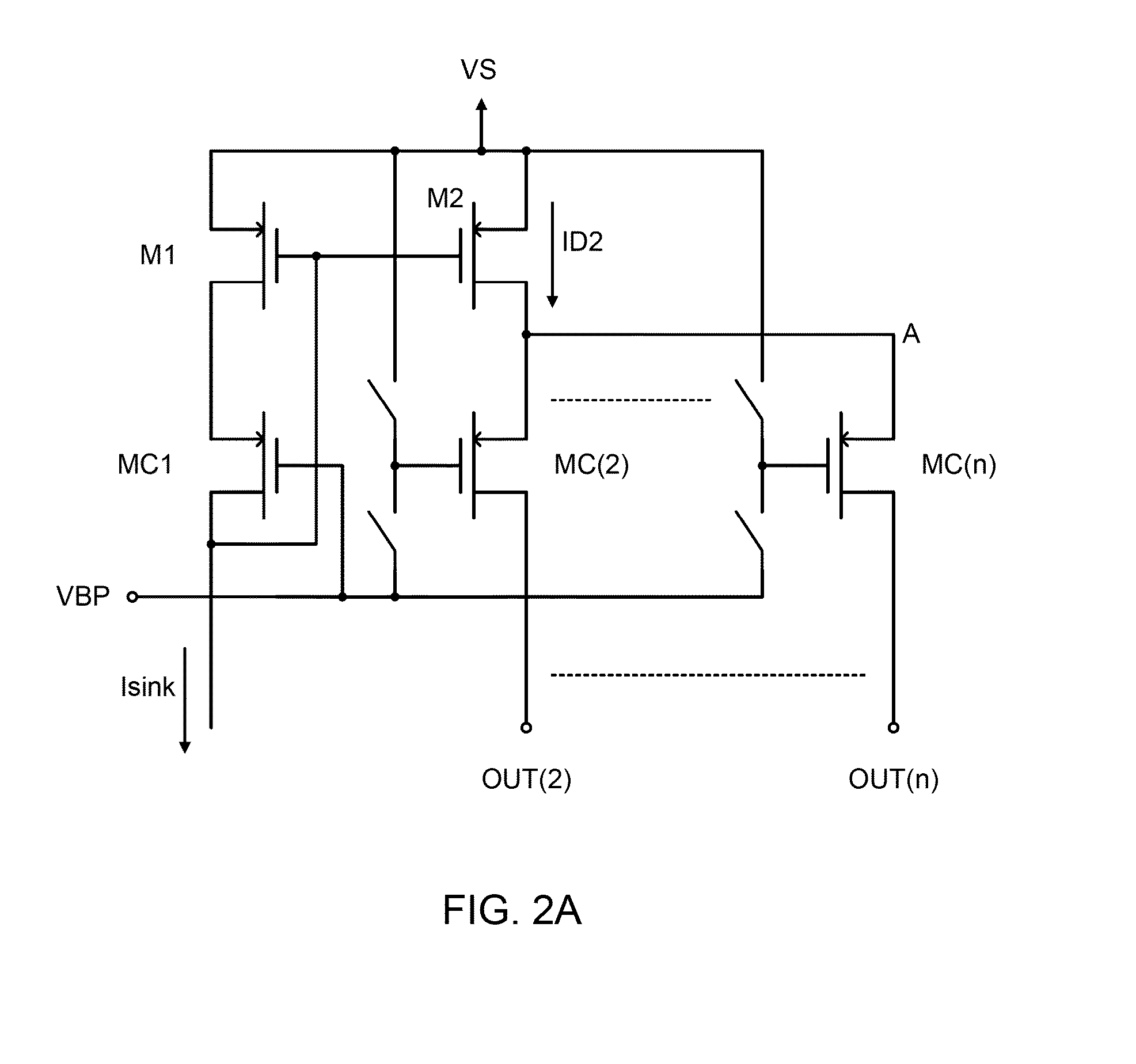
Errors regarding the amplitudes of the current delivered arise mainly due to the finite output impedance of the stimulator and any mismatch errors between the input side transistor M1 and the output side transistor M2.
However this approach could be compromised due to the different loading capacitances and loads coupled to op amp 20 when a different number of electrodes are programmed for current / stimulation delivery.
However, in many stimulator designs, the turn on times for delivering small output current levels are usually very long.
For these high voltage stimulators, very large high voltage transistors are required for the required large output current levels due to the relatively low gain of these transistors.
Also, due to the relatively high threshold voltages associated with these high voltage transistors, it will take longer time to have the small current outputs charging up the gate-to-source voltages to higher than the threshold voltages in order to turn on these high voltage transistors.

Method used


Image

  • Current sensing multiple output current stimulators
  • Current sensing multiple output current stimulators
  • Current sensing multiple output current stimulators

Examples


Embodiment Construction

[0035]Referring now to FIG. 3, there is shown an overall block diagram of one example of a multiple output current stimulator system, and specifically, one embodiment of a pulse generator. The system includes both an anodic multiple output stimulator block 10A and a cathodic multiple output stimulator block 10B. The system provides for selecting either an anodic or cathodic stimulator based upon tissue stimulation requirements determined by a clinician. The outputs of the anodic and cathodic stimulators are selected by setting the corresponding “bits” in digital registers 2. Digital registers 2 generate digital control signals DCS, which control the selection of the anodic and cathodic stimulators. Although FIG. 3 discloses two stimulators 10A and 10B, the discussion below with reference to FIGS. 4A and 4B focuses solely on the anodic stimulator 10A. It is to be understood that in some embodiments a complementary circuit for the cathodic stimulator (not shown in FIG. 4A or 4B) funct...


PUM


Abstract

A multiple output current stimulator circuit with fast turn on time is described. At least one pair of input side and output side transistors is arranged in a current mirror connected to a supply transistor by cascode coupling. The output side transistor supplies stimulation current to an electrode in contact with tissue. An operational amplifier connected to a reference voltage and to the output side transistor drives the supply transistor to maintain the voltage at the output side transistor equal to the reference voltage. The at least one pair of transistors includes multiple pairs of transistors whose output side transistors drive respective electrodes with stimulation currents. The stimulator determines the initiation and duration of stimulation current pulses supplied to each electrode. At circuit activation, large currents are generated which discharge capacitances in the output side transistors causing rapid output side transistor turn on.

Description

[0001]This application claims the benefit of U.S. Provisional Application No. 61 / 788,871, filed on Mar. 15, 2013. The subject matter of the aforementioned application is hereby incorporated by reference herein in its entirety.FIELD OF THE INVENTION[0002]The present invention relates to a current mirror circuit capable of a broad range of uses requiring controlled delivery of electrical current and finding particular utility in functional electrical stimulation (FES) applications.BACKGROUND OF THE INVENTION[0003]Typically in FES applications, current stimulators are used for providing programmable current pulses directed through an electrode to stimulate targeted neuromuscular tissue. The amplitude and duration of the current pulses delivered through the electrode are usually programmed through a digital to analog converter (DAC). The current output from the DAC is normally amplified to the desired output current amplitude at the current stimulator. The current amplification is typic...

Claims


Application Information

Patent Timeline
Patent Type & Authority Patents(United States)
IPC IPC(8): A61N1/00A61N1/36H03K3/012
CPCA61N1/36125A61N1/36071A61N1/36146H03K3/012A61N1/36003A61N1/3605Y10T307/406H03K3/023
Inventor LEE, EDWARD K. F.
Owner ALFRED E MANN FOUND FOR SCI RES
Learn More