
Bandwidth control device, bandwidth control method, and wireless network system

a bandwidth control and wireless network technology, applied in data switching networks, instruments, frequency-division multiplexes, etc., can solve problems such as the difficulty of efficiently performing bandwidth allocation for traffic flowing through the same link, the problem of how to control bandwidth allocation among traffic, and the likely monopoly of bandwidth, so as to achieve the effect of accommodating more traffic and maintaining traffic communication quality

Active Publication Date: 2016-09-13
NEC CORP
View PDF10 Cites 0 Cited by
  • Summary
  • Abstract
  • Description
  • Claims
  • Application Information

AI Technical Summary

Benefits of technology

The present invention provides a method for controlling bandwidth in a wireless network to ensure reliable communication and efficient use of network resources. By calculating the stability level of the network and the utilization rate of the bandwidth by different traffic, a link bandwidth can be allocated to each traffic demand, ensuring smooth traffic communication and accommodating more traffic without degrading quality. Previous methods only considered stability level and not utilization rate, resulting in limited bandwidth control. The present invention offers better bandwidth control and ensures optimal network performance.

Problems solved by technology

However, because a link bandwidth varies with the passage of time in the case of the above-described wireless link, it is difficult to efficiently perform bandwidth allocation for traffic flowing through the same link.
It is to be noted that if bandwidth control or priority control such as the bandwidth allocation is not performed, traffic having the largest traffic amount at that time is likely to monopolize a bandwidth.
Consequently, a problem to be solved is how to control bandwidth allocation among traffic.

Method used


Image

  • Bandwidth control device, bandwidth control method, and wireless network system
  • Bandwidth control device, bandwidth control method, and wireless network system
  • Bandwidth control device, bandwidth control method, and wireless network system

Examples


example 1

[0096]As a first example of the present exemplary embodiment, an example in which two pieces of traffic (hereinafter referred to as traffic A and traffic B) use the same link will be shown. When the stability level of the link bandwidth is that as illustrated in FIG. 5A, bandwidths are allocated to two pieces of traffic based on utilization rates.

[0097]Here, for the traffic A, the utilization rate of 0 to 20 Mbps is assumed to be 100 and the utilization rate of 20 to 60 Mbps is assumed to be 80. In addition, for the traffic B, the utilization rate of 0 to 20 Mbps is assumed to be 100 and the utilization rate of 20 to 40 Mbps is assumed to be 50.

[0098]In this case, for the traffic A, the path control unit 202 allocates a bandwidth of the stability level 100 at 20 Mbps and a bandwidth of the stability level 90 at 40 Mbps. Likewise, for the traffic B, the path control unit 202 allocates a bandwidth of the stability level 100 at 20 Mbps and a bandwidth of the stability level 70 at 20 Mb...

example 2

[0101]As a second example of the present exemplary embodiment, a process of the path control unit 202 when a CIR, an average rate, and a peak rate of traffic are each known will be described.

[0102]In this case, in each link, bandwidths obtained from a stability level of a link bandwidth (i.e., a bandwidth capable of being maintained at a minimum by each link, an average bandwidth of each link, and a maximum bandwidth capable of being realized by each link) are used.

[0103]The bandwidth of capable of being maintained at a minimum by each link and the maximum bandwidth capable of being realized by each link can be obtained using threshold values of a stability level serving as references. That is, the bandwidth capable of being maintained at a minimum by each link is obtained by setting a stability level considered as a lower limit and determining a maximum bandwidth satisfying the stability level of the lower limit. In addition, the maximum bandwidth capable of being realized by each ...

example 3

[0112]A third example of the present exemplary embodiment relates to the case in which a bandwidth of traffic is classified so that the utilization rate is most consistent with the stability level of the link bandwidth as an example of a bandwidth allocation method in a process of the path control unit 202 of step S2.

[0113]Here, it is assumed that the stability levels corresponding to bandwidths of a link are 100 at 0 to 40 Mbps, 90 at 0 to 80 Mbps, and 50 at 80 to 108 Mbps.

[0114]First, a bandwidth of traffic is classified so that the values of utilization rates are as close as possible the values of the stability levels of the link.

[0115]FIG. 7 is an explanatory diagram illustrating a traffic classifying method to be performed by the path control unit 202 of the path control device.

[0116]In order to classify a bandwidth of traffic so that the values of utilization rates are as close as possible the values of stability levels of a link bandwidth, it is possible to classify the bandw...


PUM


Abstract

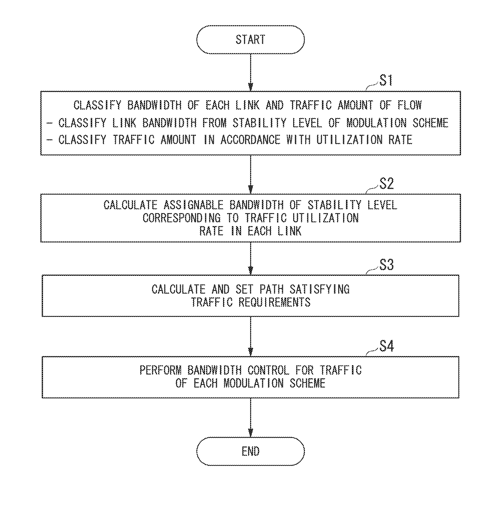
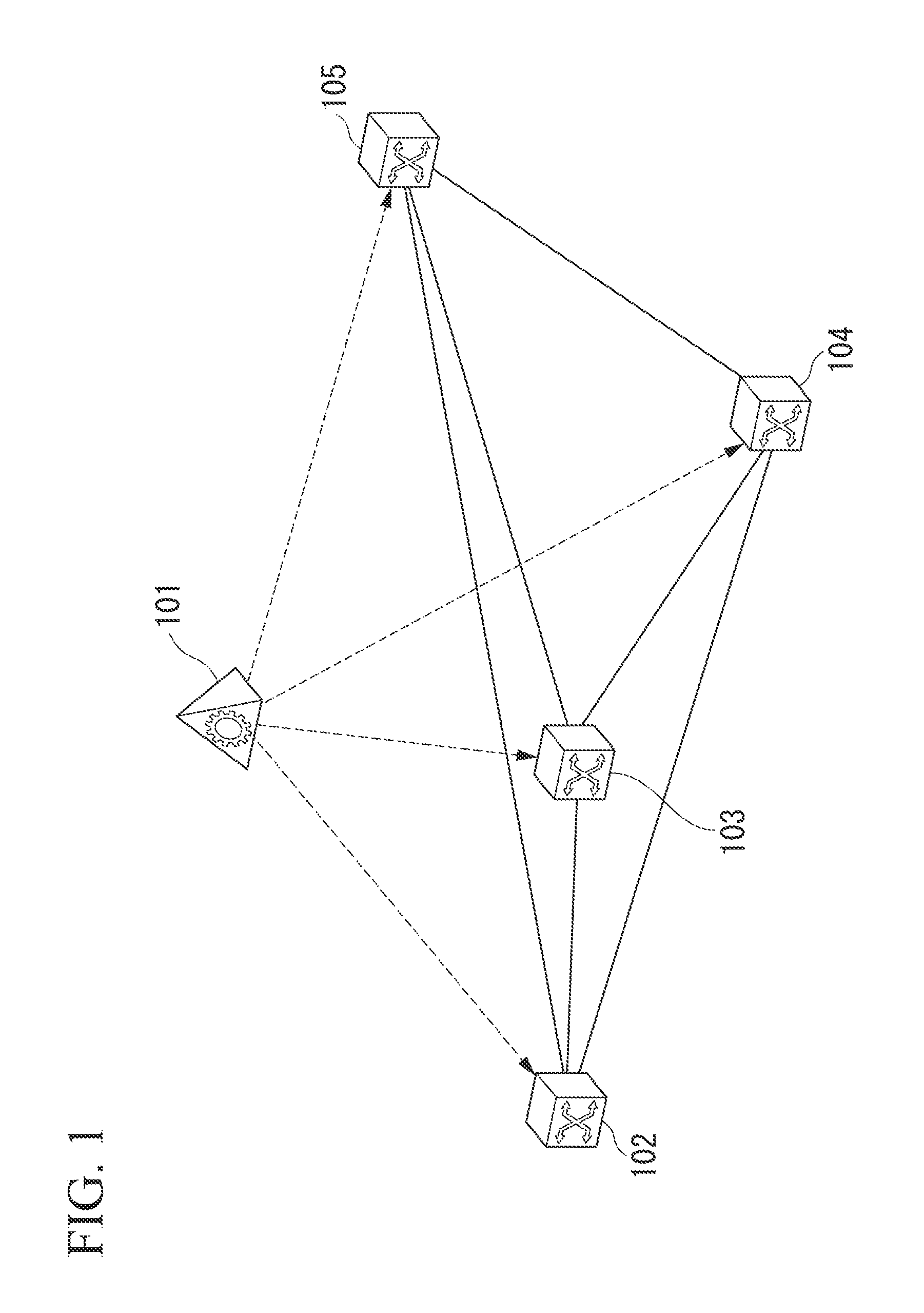
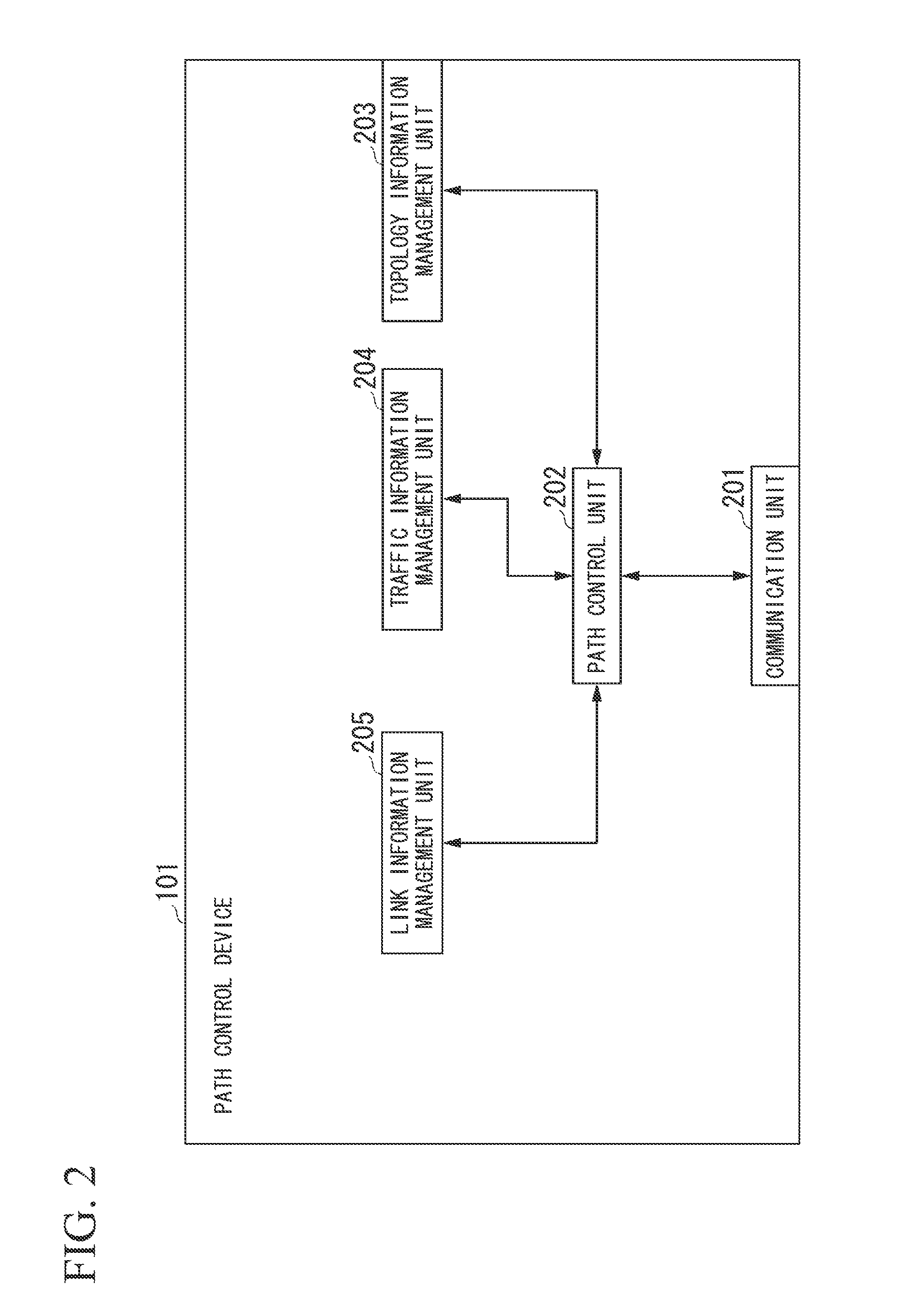
In a network configured using a wireless link in which a transmission rate fluctuates, accommodation efficiency of traffic is improved while communication quality of VBR traffic is maintained. A bandwidth control device includes a stability level calculation unit which calculates a stability level indicating a probability that a bandwidth is available in a wireless link using adaptive modulation, a utilization rate calculation unit which calculates a utilization rate of a bandwidth used by traffic to be accommodated, an allocation unit which allocates, to the traffic, a link bandwidth of the stability level corresponding to the utilization rate of the traffic, and a path control unit which sets a path for the traffic in the wireless network including a communication device that performs communication over the wireless link based on the allocated link bandwidth.

Description

TECHNICAL FIELD[0001]The present invention relates to a bandwidth control device of a wireless network, a bandwidth control method of a wireless network, and a wireless network system. In particular, the present invention relates to a bandwidth control device, a bandwidth control method, and a wireless network system which perform bandwidth control of traffic for a network configured with a wireless link using adaptive modulation.BACKGROUND ART[0002]In mobile telephone networks, communication based on fixed wireless access (FWA) using millimeter waves is widely used. Communication quality of a wireless link is affected by a wireless environment such as a signal to noise ratio (SNR) of a received signal. Accordingly, in order to realize a wireless link having a broader band, adaptive modulation technology is being focused on.[0003]The adaptive modulation technology is technology which adaptively finds and employs a modulation scheme with which transmission efficiency is best from a w...

Claims


Application Information

Patent Timeline
Patent Type & Authority Patents(United States)
IPC IPC(8): H04W28/14H04W28/10H04W28/18
CPCH04W28/18
Inventor NISHIOKA, JUN
Owner NEC CORP
Learn More