
Cathodic protection automated current and potential measuring device for anodes protecting vessel internals

a technology of cathodic protection and measuring device, applied in the field of catalytic protection, can solve the problems of inability to observe directly the galvanic anode, high potential of magnesium anodes in vessel protection applications, and inability to detect high potential anodes, etc., to achieve the effect of convenient measuremen

Active Publication Date: 2016-09-13
SAUDI ARABIAN OIL CO
View PDF48 Cites 0 Cited by
  • Summary
  • Abstract
  • Description
  • Claims
  • Application Information

AI Technical Summary

Benefits of technology

Enables safe and efficient monitoring of galvanic anode conditions, reducing the risk of accidents and labor costs while maintaining effective corrosion protection for fluid-containing vessels.

Problems solved by technology

Magnesium anodes often demonstrate high potential and, thus, corrode in less than one year in vessel protection applications.
Direct observation of the galvanic anodes is often not feasible due to their location within the interior chamber of the fluid-containing vessel.
Current and voltage measurements associated with the cathodic protection system enable an operator to assess the wear conditions of these galvanic anodes, but taking these measurements can be a dangerous, time-consuming and labor-intensive process.

Method used


Image

  • Cathodic protection automated current and potential measuring device for anodes protecting vessel internals
  • Cathodic protection automated current and potential measuring device for anodes protecting vessel internals
  • Cathodic protection automated current and potential measuring device for anodes protecting vessel internals

Examples


Embodiment Construction

[0020]The present invention will now be described more fully hereinafter with reference to the accompanying drawings which illustrate embodiments of the invention. This invention may, however, be embodied in many different forms and should not be construed as limited to the illustrated embodiments set forth herein. Rather, these embodiments are provided so that this disclosure will be thorough and complete, and will fully convey the scope of the invention to those skilled in the art.

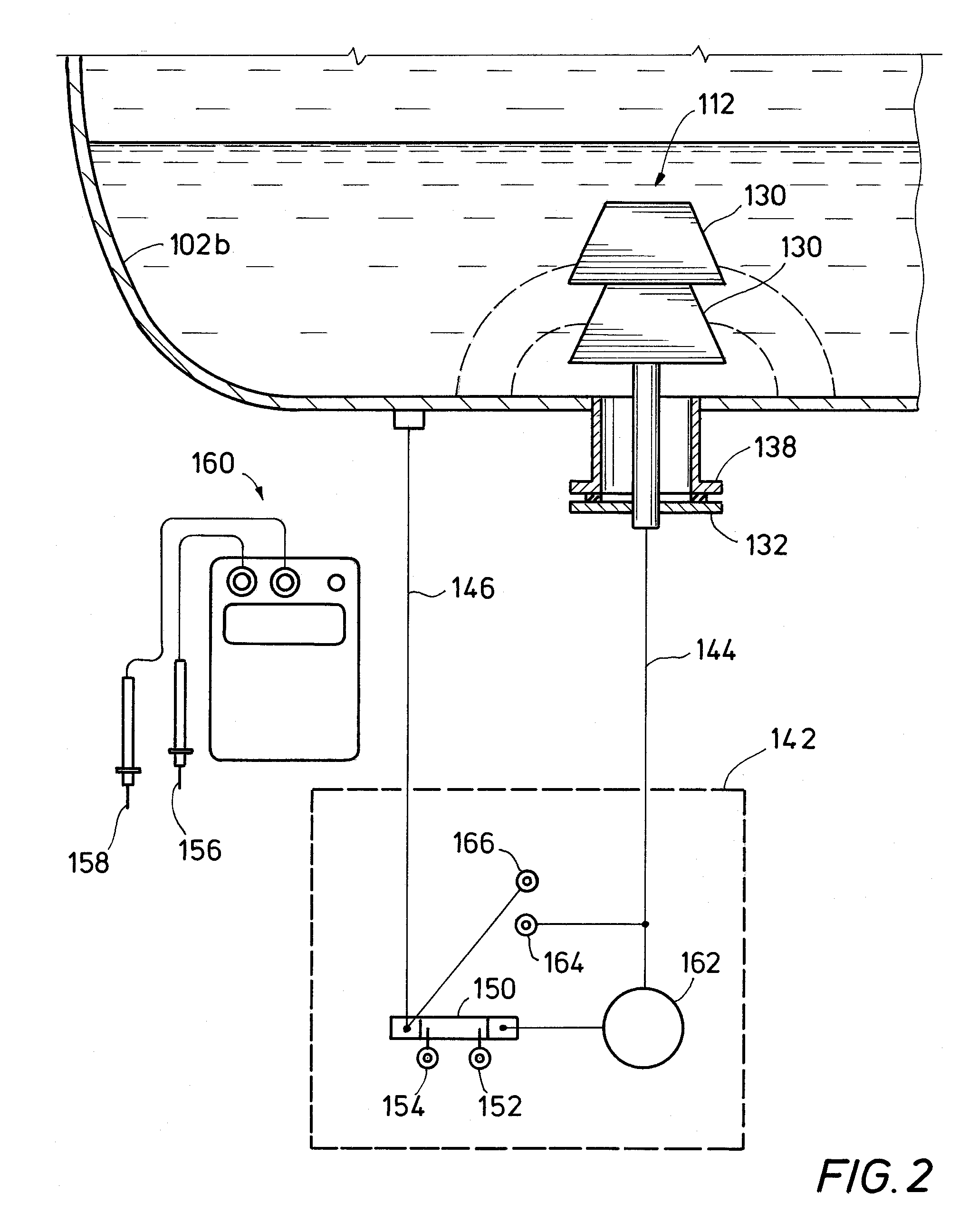
[0021]Cathodic protection system 100 is depicted in FIG. 1. Cathodic protection system 100 includes fluid-containing vessel 102, which includes wall 102a having interior surface 102b. Wall 102a of fluid-containing vessel 102 is constructed of steel and is configured for storing or separating a fluid such as wet crude in an interior chamber of fluid-containing vessel 102. As one of skill in the art will appreciate, wet crude is crude oil having droplets of water suspended therein. Over time, the water dro...


PUM

PropertyMeasurementUnit
temperatureaaaaaaaaaa
temperaturesaaaaaaaaaa
electrical resistanceaaaaaaaaaa

Abstract

Embodiments of systems and methods for providing cathodic protection to a fluid-containing vessel include measuring two distinct voltages at a junction box exterior to the fluid-containing vessel. The first voltage is measured across a shunt in the junction box such that a current magnitude through the shunt can be determined using Ohm's Law that is representative of a current output of one or more sacrificial anodes disposed within the fluid-containing vessel. The second voltage is measured by depressing a pushbutton of a momentary switch to open the switch and interrupt current flow through the shunt. The second voltage is representative of a voltage difference between the one or more sacrificial anodes and the a wall of the fluid-containing vessel.

Description

BACKGROUND OF THE INVENTION[0001]1. Field of the Invention[0002]Embodiments of the present invention relate generally to cathodic protection of structures in corrosive environments. In particular, embodiments of the invention relate to systems and methods for monitoring the condition of galvanic anodes disposed internally within a fluid-containing vessel for the cathodic protection of the fluid-containing vessel.[0003]2. Description of the Related Art[0004]Cathodic protection systems are often employed for the protection of metallic structures from corrosion. The protected metallic structures are arranged to serve as a cathode in an electrical circuit such that oxidation of the metallic structures are restricted. A sacrificial anode is often supplied to the circuit to support a net oxidation reaction.[0005]One type of metallic structure that is often protected by a cathodic protection system is a fluid-containing vessel such as a storage tank, cylinder, settling tank or process equi...

Claims


Application Information

Patent Timeline
Patent Type & Authority Patents(United States)
IPC IPC(8): C23F13/00C23F13/04C23F13/22C23F13/14
CPCC23F13/04C23F13/22C23F13/14
Inventor AL-ZAHRANI, MOHAMMAD G.
Owner SAUDI ARABIAN OIL CO
Learn More