
Sound deadening baffle for a ventilation valve

a technology for venting valves and baffles, which is applied in the direction of vehicle heating/cooling devices, transportation and packaging, building components, etc., can solve the problems of comparatively high cost and limited efficiency of noise protection caps, and achieve simple and cost-effective measures to reduce the unwelcome entry of sound into the interior of the vehicl

Active Publication Date: 2016-09-13
ILLINOIS TOOL WORKS INC
View PDF43 Cites 7 Cited by
  • Summary
  • Abstract
  • Description
  • Claims
  • Application Information

AI Technical Summary

Benefits of technology

[0005]The object of the invention is to reduce the undesired admission of sound into the vehicle interior by simple and cost-effective measures in the field of the venting valve.
[0006]To achieve this object, a baffle for a venting valve is provided according to the invention for reducing the sound admission into the interior in particular of a motor vehicle, including at least one air guiding channel having a labyrinth geometry. The invention is based on the basic idea to provide the venting valve with an add-on part having a simple structure and preventing or at least reducing the sound admission into the interior. The labyrinth geometry of the venting channel results in that large part of the sound waves are reflected and reverberated to the outside. It is not necessary to use expensive absorption materials. The labyrinth geometry permits with little expenditure to realize the desired reflection geometry without the flow cross-section of the air guiding channel necessary for the air exchange being noticeably reduced.

Problems solved by technology

However, it became apparent that the efficiency of such noise protection caps is very limited.
Furthermore, the noise protection caps are comparatively expensive as their manufacturing is complicated.

Method used


Image

  • Sound deadening baffle for a ventilation valve
  • Sound deadening baffle for a ventilation valve
  • Sound deadening baffle for a ventilation valve

Examples


Embodiment Construction

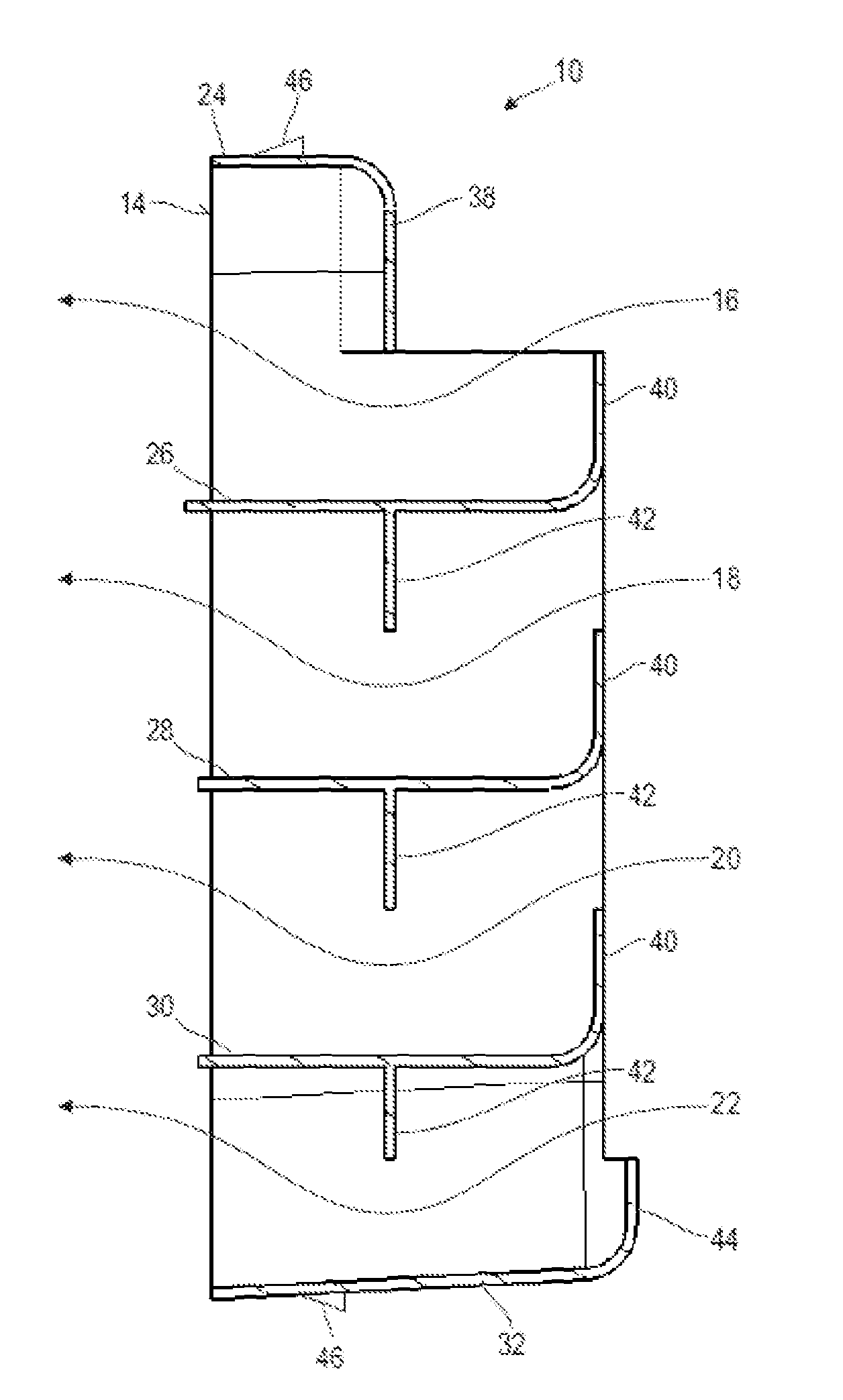
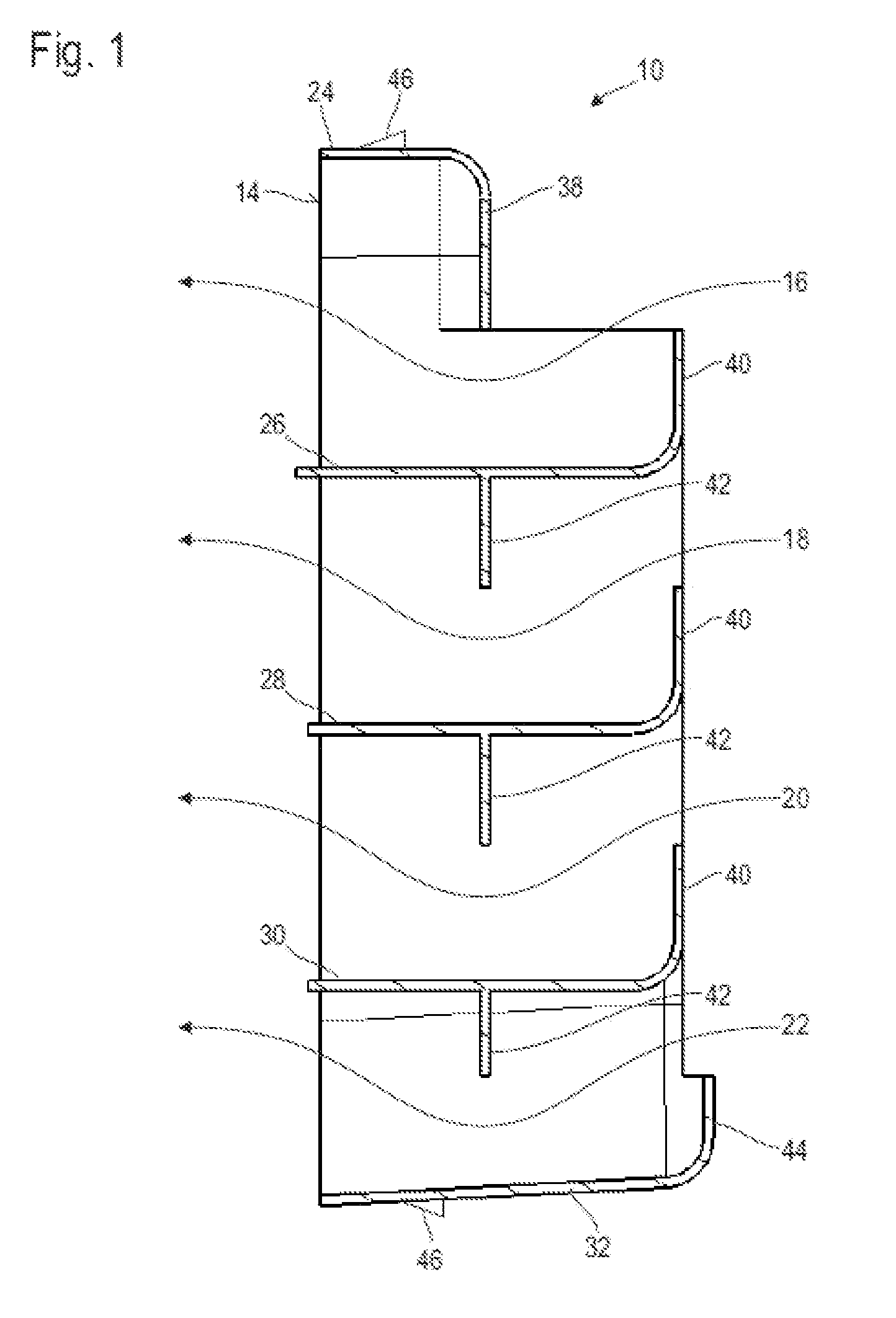
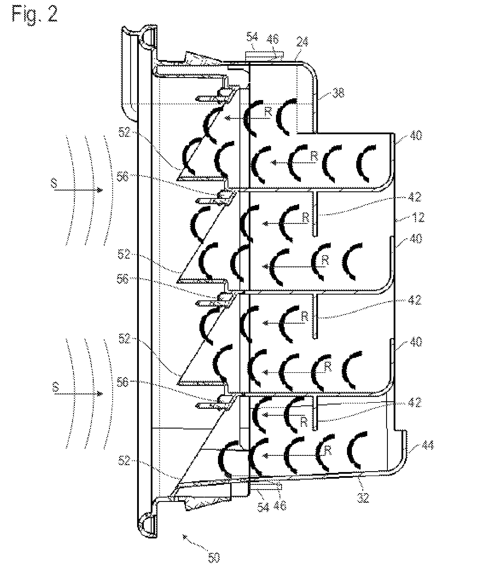
[0024]FIG. 1 shows in a sectional view a baffle 10 which in the present case is configured as a one-piece plastic body having in the broadest sense a parallelepipedal shape. A total of four air guiding channels 16, 18, 20, 22, indicated by the flow arrows shown in FIG. 1 extend through the baffle from an inlet side 12 to an outlet side 14. The air guiding channel 16 is delimited between an upper outer wall 24 and an intermediate wall 26 which forms the bottom for the air guiding channel 16 and the upper face of the air guiding channel 18 below. On its upper face, the air guiding channel 18 is delimited by the intermediate wall 26, and on the bottom side by a further intermediate wall 28. The air guiding channel 20 for its part is delimited by the intermediate wall 28 and by a further intermediate wall 30. Finally, the air guiding channel 22 is delimited by the intermediate wall 30 and by an outer wall 32 of the baffle 10 arranged in the bottom part. Laterally, each air guiding chann...


PUM


Abstract

A baffle (10) for a venting valve for reducing the admission of sound into the interior in particular of a motor vehicle, including at least one air guiding channel (16, 18, 20, 22) having a labyrinth geometry.

Description

RELATED APPLICATIONS[0001]This application corresponds to PCT / EP2011 / 001053, filed Mar. 3, 2011, which claims the benefit of German Application No. 10 2010 010 927.4, filed Mar. 10, 2010, the subject matter, of which are incorporated herein by reference in their entirety.BACKGROUND OF THE INVENTION[0002]The invention relates to a baffle for a venting valve for reducing the sound admission into the interior in particular of a motor vehicle.[0003]Venting valves for the vehicle interior are generally known. They serve to evacuate the air supplied to the vehicle interior through a ventilating and / or air conditioning system to the outside. Such a venting valve usually has a plurality of check valves which permit the exit of the air out of the vehicle interior but prevent the undesired penetration of outside air and of dirt and water.[0004]In order to satisfy increasing comfort requirements, different attempts have already been made to reduce the undesired admission of sound into the vehi...

Claims


Application Information

Patent Timeline
Patent Type & Authority Patents(United States)
IPC IPC(8): B60H1/24
CPCB60H1/248B60H1/00592B60H2001/00092B60H2001/006
Inventor HOFMANN, JUERGENLEIDNER, VITALI
Owner ILLINOIS TOOL WORKS INC
Learn More