Cutting system for glass substrate

a cutting system and liquid crystal display technology, applied in the field of liquid crystal display, can solve the problems of unbalanced handling force, leftover , i>b /i>, etc., and achieve the effect of ensuring the quality of the unit panel, facilitating swing or transversal movement, and correct and stable operation of the sucking board

Active Publication Date: 2016-09-06
TCL CHINA STAR OPTOELECTRONICS TECH CO LTD
View PDF9 Cites 0 Cited by
  • Summary
  • Abstract
  • Description
  • Claims
  • Application Information

AI Technical Summary

Benefits of technology

[0021]The present invention provides an additional discharging device in the cutting system for glass substrate. A vacuum is created to hold up the leftover so as to directly sever the leftover from with the unit panel of the glass substrate. On the other hand, with the help of the robot arm, the sucking board can readily conduct a swing or transversal movement so as to ensure the correct and stable operation of the sucking board in both angle as well as speed. In addition, since the leftover is securely attached onto the surface of the sucking board through the vacuum, the surface area for contact between the leftover and the sucking board is increased. As a result, the leftover is exerted with even severing force. Because the leftover is securely held by the sucking board, once it is severed, the leftover will not create any unwanted and unnecessary contact with the unit panel so as to prevent the later from being damaged or scratched. Therefore, the quality of the unit panel is ensured.

Problems solved by technology

However, the dimension of the leftover 112b is comparably small and when it is handled by the sucking disks 160, there isn't enough contact area such that the leftover 112b is exerted with unbalanced handling force.

Method used


Image

  • Cutting system for glass substrate
  • Cutting system for glass substrate
  • Cutting system for glass substrate

Examples


embodiment 2

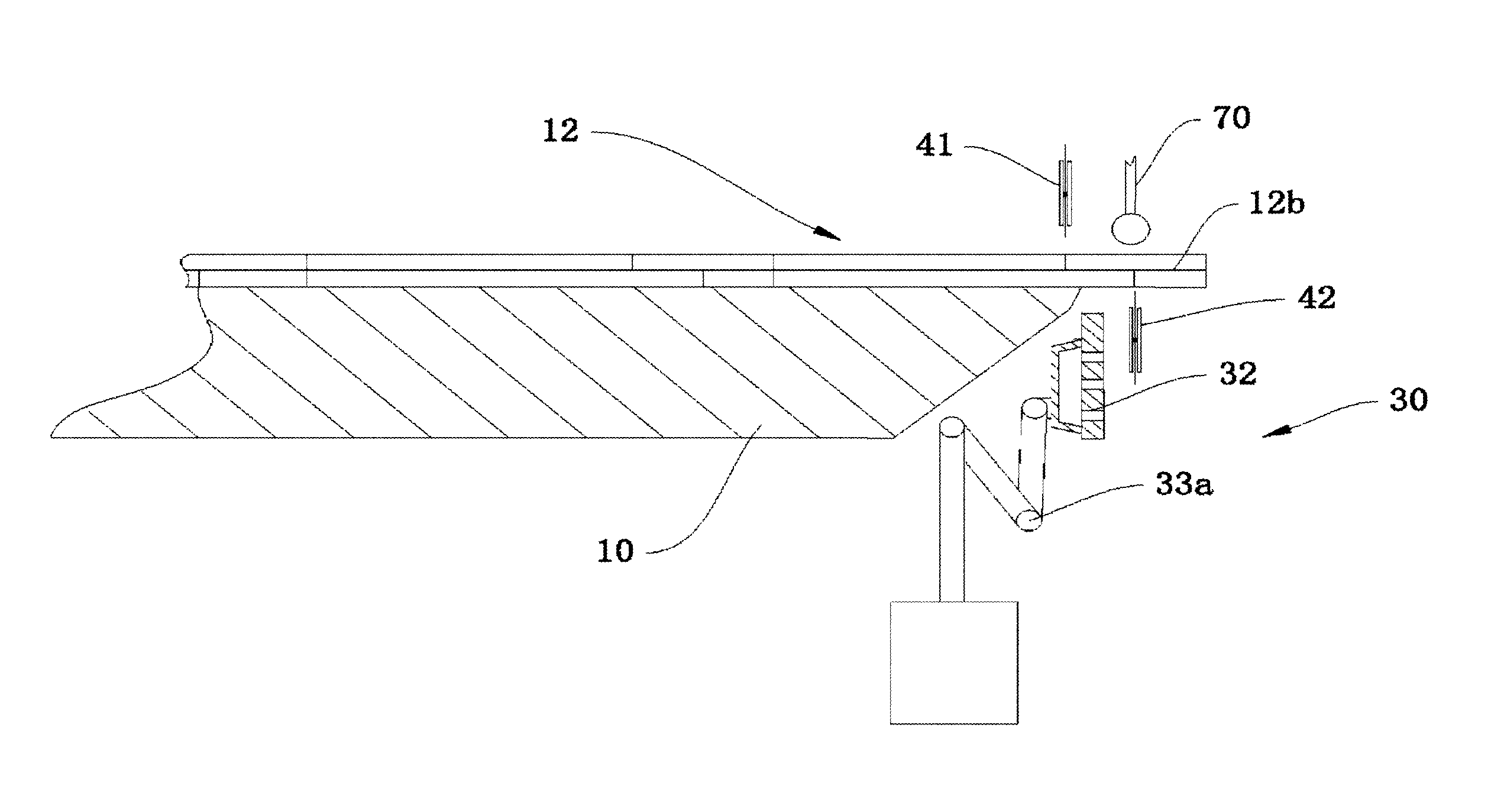
[0046]In the current embodiment, as shown in FIG. 7, the sucking board 30 is not interlinked to the front end of the upstream table 10, while it is displaced directly by the movement of the robot arm 33a. Once the sucking board 30 holds up the leftover 12b, it can be moved to separate the leftover 12b from the glass substrate 12 and transfer it to the collecting bin 50 directly.

[0047]On the other hand, a roller 70 is arranged above the glass substrate 12 in align with the lower knife 42. By this arrangement, the cutting stroke of the upper knife 41 and the lower knife 42 can be operated in different timing so as to meet different field requirements. For example, the lower knife 42 can proceed the cutting stroke firstly to the color filter substrate of the glass substrate 12 with the roller 70 pressing down the glass substrate 12 for balancing the cutting force applied to the glass substrate 12 by the lower knife 42. The arrangement of the roller 70 can readily protect the glass subs...


PUM

PropertyMeasurementUnit
suction forceaaaaaaaaaa
dimensionsaaaaaaaaaa
dimensionaaaaaaaaaa

Abstract

A system is provided for cutting a glass substrate that is movably carried on an upstream table. A transferring device is provided for displacing the glass substrate from the upstream table to a downstream table. A cutting device is arranged between the upstream and downstream tables for cutting the glass substrate. A discharging device is arranged between the upstream and downstream tables for removing a leftover of the glass substrate and includes a vacuum pump. A sucking board that has orifices defined thereon is combined with a sucking chamber that is in communication with the orifices and the vacuum pump such that the leftover can be firmly held on the sucking board. A displacing device is interconnected to the sucking board for maneuvering the sucking board to displace the sucking board along with the leftover firmly held thereon.

Description

FIELD OF THE INVENTION[0001]The present invention relates to a technological field of liquid crystal display, and more particularly, to a cutting system for glass substrate of the liquid crystal display.DESCRIPTION OF PRIOR ART[0002]A typical glass substrate generally is configured with upper and lower TFT substrates, a color filter substrate, and liquid crystal between the upper and lower TFT substrates. The furnished glass substrate is tailored to different dimensions according the field requirements. The existing cutting apparatus includes an upper sucking table, and a lower sucking table with upper and lower knifes arranged between gap of the upper and lower sucking tables. A furnished glass substrate is cut on that cutting apparatus.[0003]As shown in FIG. 1, the glass substrate blank 112 is marked with preset cutting line dividing the blank 112 into the unit panel 112a (having larger dimension), and the leftover 112b (with smaller area). With the help of a transfer robot 111, t...

Claims


Application Information

Patent Timeline
Patent Type & Authority Patents(United States)
IPC IPC(8): C03B33/02C03B33/033B26D1/24C03B33/03B26D7/18B26D7/01B65G49/06B26D7/00
CPCB26D7/018B26D1/245B26D7/1863B65G49/068C03B33/03C03B33/033B26D2007/0018B65G2249/045Y10T83/0453Y10T83/207
Inventor HUANG, HAIBO
Owner TCL CHINA STAR OPTOELECTRONICS TECH CO LTD
Why Eureka
Try Eureka