
Method and system for monitoring the performance of a heat exchanger

a technology of fluid heat exchanger and heat exchanger body, which is applied in the direction of heat measurement, turbine/propulsion fuel heating, instruments, etc., can solve the problems of reducing oil cooling and fuel heating, and achieve the effect of no weight burden and no cost increas

Active Publication Date: 2016-08-30
ROLLS ROYCE PLC
View PDF15 Cites 1 Cited by
  • Summary
  • Abstract
  • Description
  • Claims
  • Application Information

AI Technical Summary

Benefits of technology

The invention uses a second threshold value to alert to partial blockage in a fluid flow path, allowing for timely remediation to prevent complete blockage and associated engine performance problems and maintenance costs. The system does not require additional hardware or significant weight or cost increase.

Problems solved by technology

However, even a partial blockage of the fuel-to-oil heat exchanger may result in diminished oil cooling and fuel heating with the performance of both the oil and fuel system deviating from nominal levels for the operating condition of the engine.

Method used


Image

  • Method and system for monitoring the performance of a heat exchanger
  • Method and system for monitoring the performance of a heat exchanger
  • Method and system for monitoring the performance of a heat exchanger

Examples


first embodiment

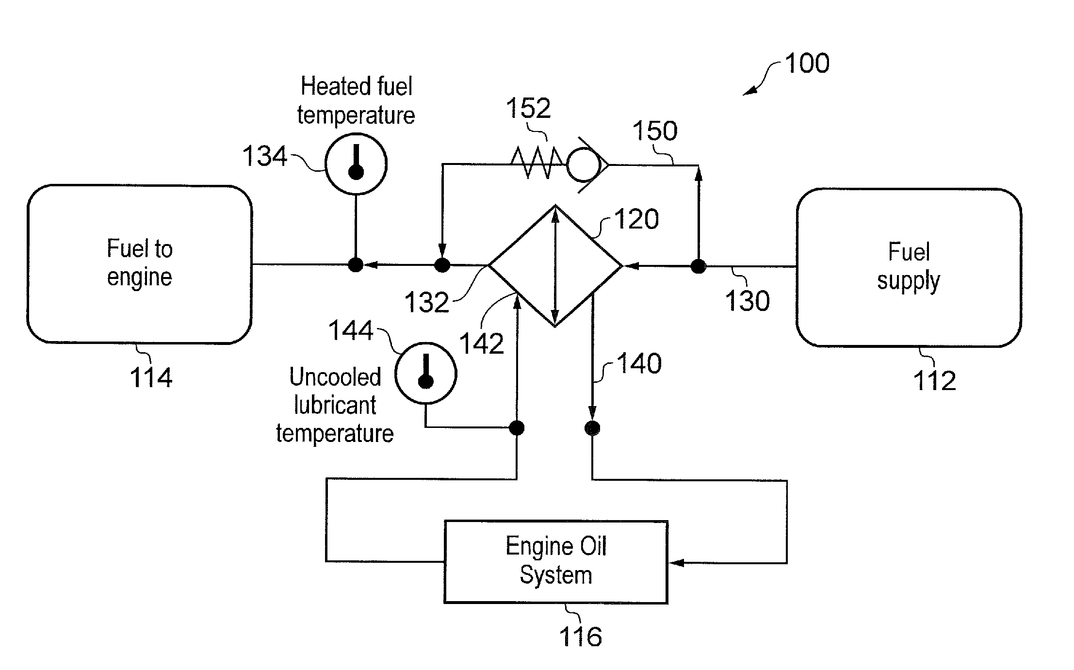
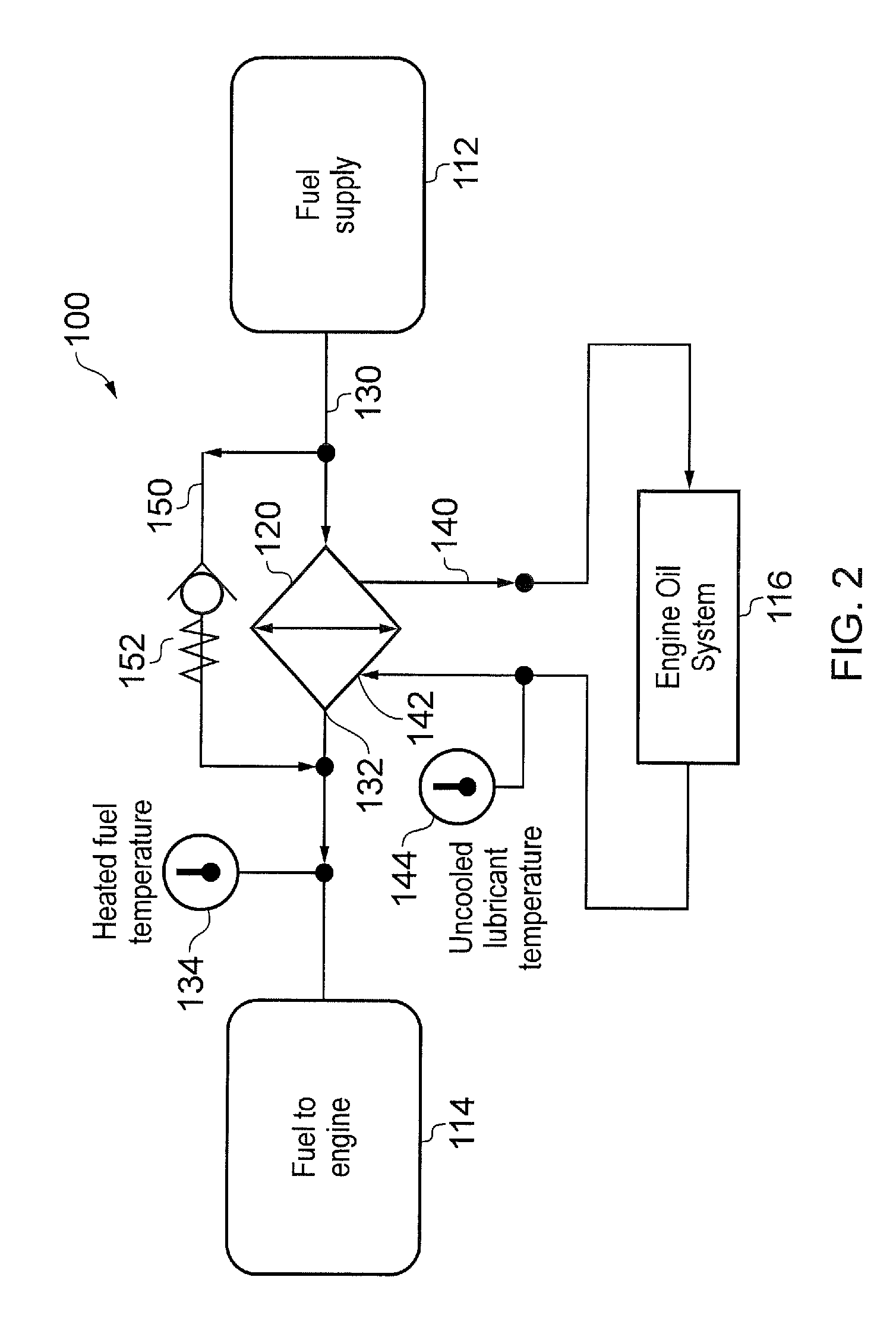
[0055]Referring to FIGS. 2 and 3, a system for monitoring the performance of a fluid heat exchanger according to the invention is designated generally by the reference numeral 100.

[0056]The system 100 comprises a fuel reservoir 112, an oil system 116 and a heat exchanger 120.

[0057]The heat exchanger 120 comprises a first fluid flow path 130 extending through the heat exchanger 120 and a second fluid flow path 140 extending through the heat exchanger 120.

[0058]In the present embodiment the first fluid flow path 130 and the second fluid flow path 140 are arranged in a cross-flow orientation within the heat exchanger 120. In other arrangements, the first fluid flow path 130 and the second fluid flow path 140 may take other orientations relative to one another.

[0059]A first temperature sensor 134 is positioned in the first fluid flow path 130 at the exit from the heat exchanger 120. A second temperature sensor 144 is positioned in the second fluid flow path 130 at the entry to the heat ...

second embodiment

[0077]Referring to FIG. 3, a system for monitoring the performance of a fluid heat exchanger according to the invention is designated generally by the reference numeral 200. Features of the system 200 which correspond to those of apparatus 100 have been given corresponding reference numerals for ease of reference.

[0078]The system 200 comprises a fuel reservoir 112, an oil system 116 and a heat exchanger 120.

[0079]The heat exchanger 120 comprises a first fluid flow path 130 extending through the heat exchanger 120 and a second fluid flow path 140 extending through the heat exchanger 120.

[0080]A bypass path 150 is provided in the first fluid flow path 130 around the heat exchanger 120. The bypass path 150 includes a non-return valve 152 that ensures that fuel passes through the heat exchanger 120 only once.

[0081]This method and system of the present invention may be applied to other gas turbine engine applications (aero / marine / industrial) using fuel-to-oil heat exchanger as the oil he...


PUM

PropertyMeasurementUnit
temperatureaaaaaaaaaa
thresholdaaaaaaaaaa
pressureaaaaaaaaaa

Abstract

A system for monitoring the performance of a fluid heat exchanger for use with an engine includes a heat exchanger having a first fluid flow path therethrough and a second fluid flow path therethrough, a first temperature sensor positioned in the first fluid flow path at an exit from the heat exchanger, a second temperature sensor positioned in the second fluid flow path at an entry to the heat exchanger, a processor and an alert generator. The processor is adapted to receive a first temperature measurement value from the first temperature sensor, and a second temperature measurement value from the second temperature sensor, the processor being further adapted to calculate a temperature difference between the first and second temperature measurement values. The alert generator is adapted to generate an alert signal to a user, the alert signal being generated if the temperature difference is greater than a threshold value.

Description

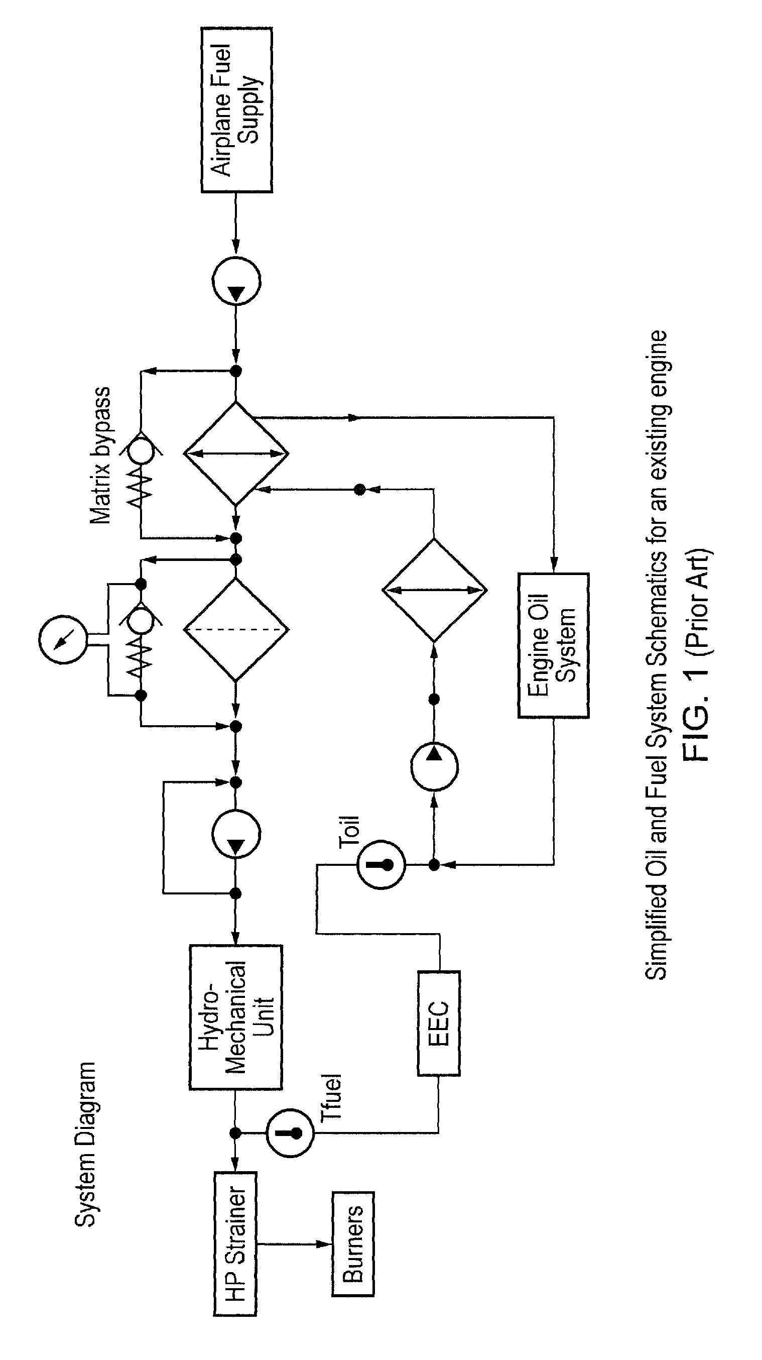
[0001]This invention claims the benefit of UK Patent Application No. 1308709.3, filed on 15 May 2013, which is hereby incorporated herein in its entirety.FIELD OF THE INVENTION[0002]The present invention relates to a method and system for monitoring the performance of a fluid heat exchanger, and particularly, but not exclusively to a method and system for monitoring the performance of a fluid heat exchanger of a gas turbine engine.BACKGROUND TO THE INVENTION[0003]In a typical aircraft engine fuel system architecture the fuel supplied to the engine(s) from the airplane's fuel tank(s) by a low pressure pump that is located upstream of a fuel-to-oil heat exchanger. The fuel-to-oil heat exchanger is the main heat sink for the engine oil and provides for both oil cooling and fuel heating.[0004]In such an engine design it is usual to incorporate a bypass flow path providing an alternate flow path for the fuel in the unlikely event that the fuel-to-oil heat exchanger becomes blocked. A typ...

Claims


Application Information

Patent Timeline
Patent Type & Authority Patents(United States)
IPC IPC(8): F28F27/00F28D21/00G01K1/16F02C7/14
CPCG01K1/16F02C7/14F28F27/00F28D2021/0021F05D2260/80Y02T50/675G01K3/005G01K3/08G01K13/02Y02T50/60F02C7/224G06F1/206
Inventor AZEEM, WAQARREID, MARK PEDEN
Owner ROLLS ROYCE PLC
Learn More