
Depth measurement quality enhancement

a depth measurement and quality enhancement technology, applied in image enhancement, image analysis, instruments, etc., can solve the problems of continuous surfaces, and achieve the effect of enhancing the quality of range finding measurements and reducing the quality of flat surfaces

Active Publication Date: 2016-08-23
SOFTKINETIC SOFTWARE
View PDF6 Cites 13 Cited by
  • Summary
  • Abstract
  • Description
  • Claims
  • Application Information

AI Technical Summary

Benefits of technology

This patent is about a method and system to improve the accuracy of range finding measurements, such as depth maps and 3D point clouds. It detects defective pixels, like noisy or interpolated "flying pixels," which can reduce the quality of flat surfaces and edges of objects in the depth map or point cloud. By reducing the noise, the method and system improve the quality of the range finding measurements and enhance the detection, identification, and tracking of user and objects in the 3D scene. This results in better modeling of user and objects and improved user experience in the 3D scene.

Problems solved by technology

However, they tend to reduce the quality of flat and continuous surfaces.

Method used


Image

  • Depth measurement quality enhancement
  • Depth measurement quality enhancement
  • Depth measurement quality enhancement

Examples


Embodiment Construction

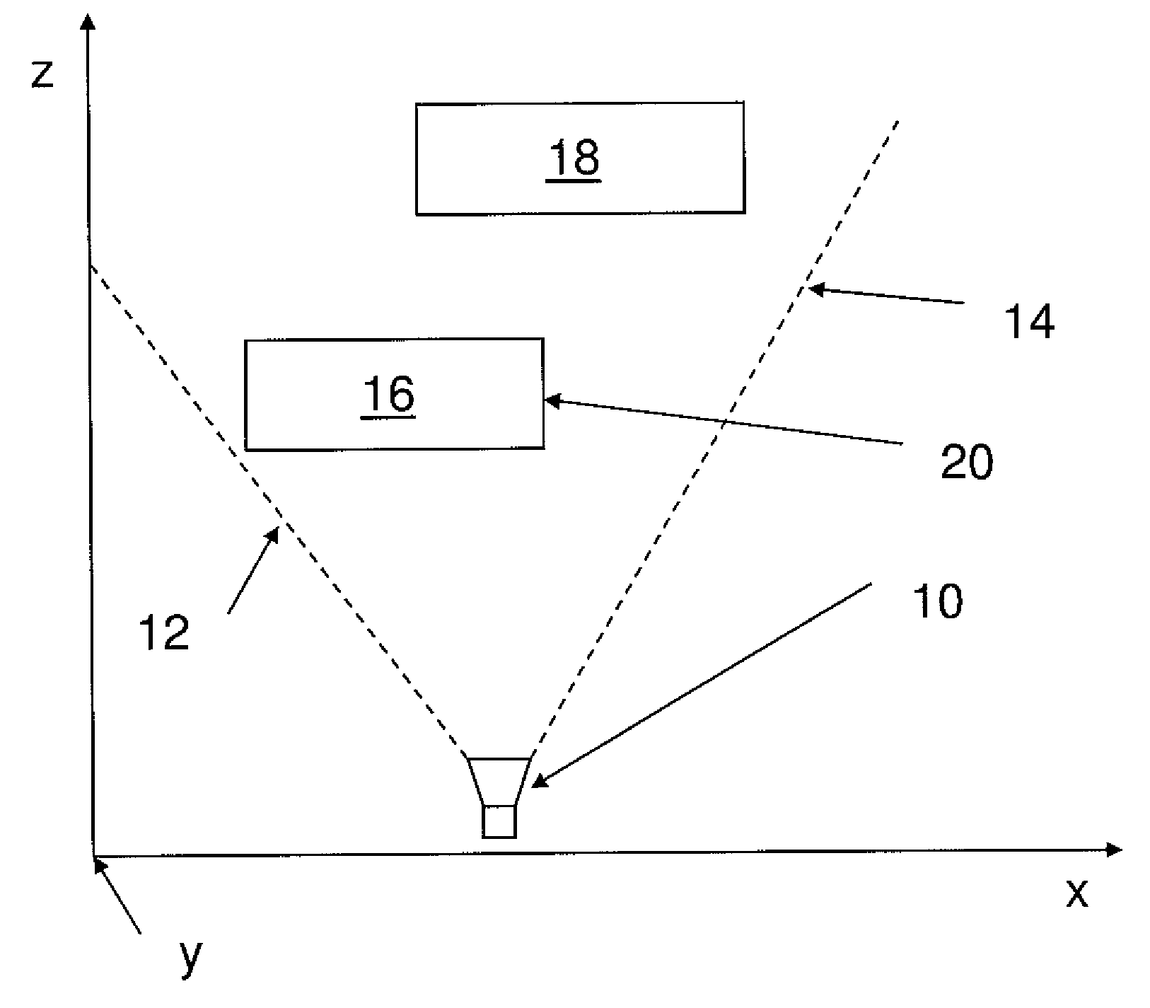
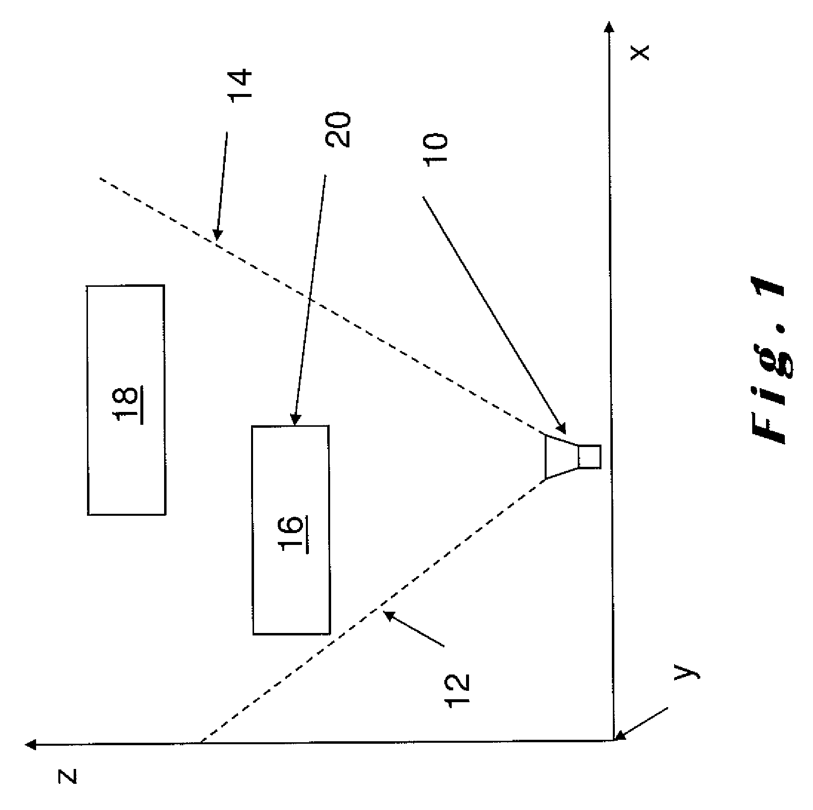
[0047]The present invention will be described with respect to particular embodiments and with reference to certain drawings but the invention is not limited thereto. The drawings described are only schematic and are non-limiting. In the drawings, the size of some of the elements may be exaggerated and not drawn on scale for illustrative purposes.

[0048]It will be understood that the terms “vertical” and “horizontal” are used herein refer to particular orientations of the Figures and these terms are not limitations to the specific embodiments described herein.

[0049]For a typical time-of-flight (ToF) 3D camera, the process of computing distance or depth data using TOF principles involves a combination of optical and electronic apparatus with analogue and digital processing units. Typically, an amplitude modulated (AM) infrared (IR) signal is sent out to the scene by the illumination system embedded in the ToF camera device. A dedicated sensor synchronously registers the IR intensity re...


PUM


Abstract

Described herein is a method for correcting defective depth values in depth map images. Defective values correspond to “noisy pixels” located on continuous flat surfaces and interpolated “flying pixels” located along an edge between a foreground object and a background object. The method comprising the steps of accessing a depth map of a scene which includes the foreground and background objects, detecting and identifying noisy and interpolated depth measurements within the depth map using a method, defining and applying a correction to each of the detected defective noisy and interpolated depth measurements using a specifically defined weighted correction factor. By providing the corrected defective depth values in depth map images, edges are sharpened in depth and continuous surfaces are flattened, enabling higher efficiency and robustness of further image processing.

Description

FIELD OF THE INVENTION[0001]The present invention relates to quality enhancement of range finding measurements, such as depth maps or images containing “three-dimensional point clouddata information, and is more particularly concerned with de-noising of depth measurements and the correction of problematic interpolated depth values associated with pixels corresponding to an edge between a foreground object and a background object in an imaged three-dimensional scene.BACKGROUND TO THE INVENTION[0002]Depth measurement camera systems are recent range finding measurement devices which have become more popular due to technologies used for gesture recognition and human skeletal tracking in consumer electronics systems and in console games.[0003]Mainly, there are two types of environment lighting independent depth sensing or three-dimensional (3D) camera technologies that are suitable for such applications. One type of 3D camera technology is the structured light 3D camera, for example, p...

Claims


Application Information

Patent Timeline
Patent Type & Authority Patents(United States)
IPC IPC(8): H04N13/00G01S17/89G06T5/00G01S17/894
CPCG01S17/89G06T5/005H04N13/0022G06T2207/10028H04N2013/0081G06T5/77H04N13/128G01S17/894G06T1/00
Inventor GUIGUES, LAURENTSAMUEL, MICHELTHOLLOT, JULIEN
Owner SOFTKINETIC SOFTWARE
Learn More