
Ocean bottom seismic node system

Active Publication Date: 2016-08-16
MAGSEIS FAIRFIELD ASA
View PDF21 Cites 5 Cited by
  • Summary
  • Abstract
  • Description
  • Claims
  • Application Information

AI Technical Summary

Benefits of technology

The invention is a seismic data acquisition system that uses multiple autonomous seismic nodes. These nodes have a primary oscillator and a reference oscillator that generates a reference frequency. The system also includes a temperature sensor, an inertial sensor, and a memory for storing recorded seismic data. A processor calculates a calibration factor based on the temperature, inertial sensor, and reference frequency. The processor repeatedly calibrates the primary oscillator at predetermined time intervals using the calibration factor to provide high precision data readings from the ocean bottom with optimal power efficiency. The system also has a reference oscillator that consumes less power and provides accurate readings over time. The use of a reference oscillator and a primary oscillator allows for more precise mapping and allows the seismic nodes to stay longer underwater once deployed. The new system will be well-suited for conducting OBS surveys at any water depth and will significantly lower the costs compared to existing systems.

Problems solved by technology

In changing marine environments and due to different weather conditions this cannot always be optimally scheduled.
Throughout the placement, oscillators in the seismic nodes may drift and thereby produce a time error in the sampled seismic data that varies due to for example temperature changes or gravitational forces.
Furthermore, the autonomous seismic nodes will have to operate for these long periods of time without any additional battery charging.
Due to precision errors in the seismic nodes or any parts thereof, much of the available hydrocarbon and gas may not be mapped with sufficient quality.
One of the major factors affecting recording precision is drift.
Drift in an oscillator causes changes in the frequency of the oscillator of the seismic node, which will results in timing errors.
The frequency drift of an oscillator will negatively impact recording precision.
It is costly and time consuming to place seismic nodes at the ocean bottom, and the weather may restrict time available for data acquisition and this may result in inadequate power to run all the electronics including the oscillators.
In addition, many types of oscillators will drift because of temperature variations etc., while others may use so much power that it will limit the number of days the electronics will function.
The physical size of existing oscillators and battery power packs required may also be a limitation.
If an ocean bottom cable with electric conductors is used, then a power supply onboard the vessel is required, but water might enter electrical terminations and connectors and thus affect the usability of the cable.
Also, the cable cannot be too long as this would cause the transmitted voltage to drop to an unacceptable level (the cable may be several kilometers long).
A clock that is affected by gravitational and temperature effects can cause a frequency shift in the oscillator frequency, thereby resulting in errors in the seismic data.
The need for lower battery power consumption along with proper dealing with frequency drift remains a major challenge for most seismic node system operations.
These issues limit the application of seismic nodes to areas where cable surveys are not an option for operational reasons, for example in the vicinity of platforms or in deep water.
The seismic nodes have been proven to be difficult to operate due to the operational difficulties mentioned above.
The methods of data acquisition described above may not be viable solutions for long duration surveys.
The efficiency of these systems is too low and may at times provide inaccurate data.

Method used


Image

  • Ocean bottom seismic node system
  • Ocean bottom seismic node system
  • Ocean bottom seismic node system

Examples


Embodiment Construction

[0057]Example embodiments will be described with reference to the drawings. The same reference numerals are used for the same or similar features in all the drawings and throughout the description.

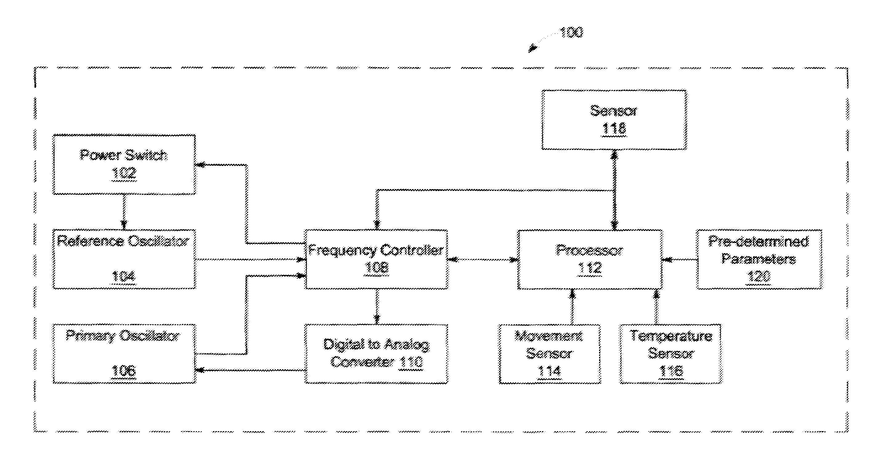
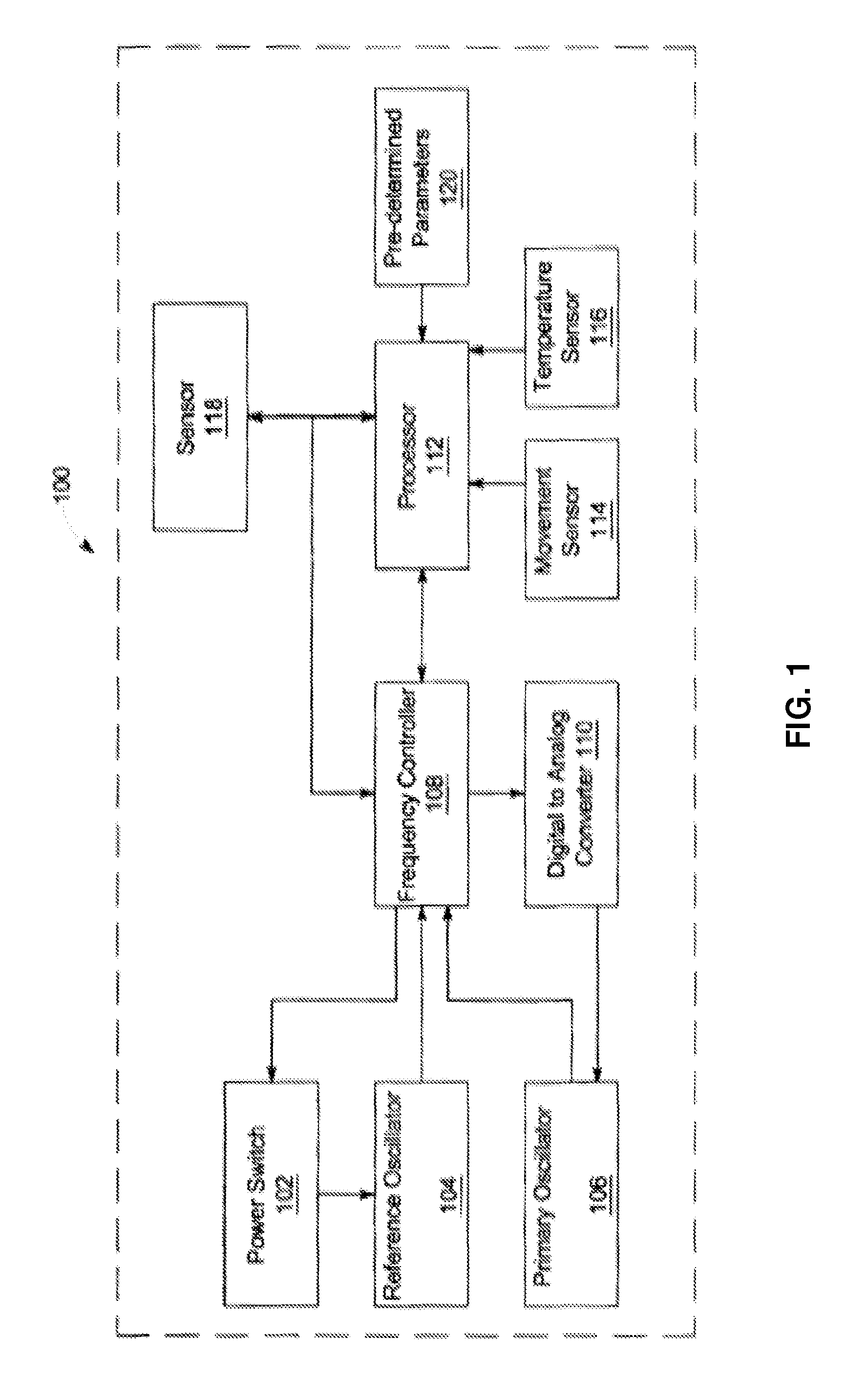
[0058]FIG. 1 illustrates a block diagram of a seismic node apparatus. The description of FIG. 1 includes a general description of an autonomous seismic node 100 that include a primary oscillator 106 and a reference oscillator 104 and a computing environment for which the embodiments may be implemented.

[0059]Various embodiments may be practiced with a computer, a mainframe computer or combinations that include workstations with servers. Program modules include routines, programs, objects, components and data structures for performing tasks, processing data, and recording and displaying information.

[0060]Embodiments may be practiced with various system configurations that separately or in combination with the seismic node or an autonomous seismic node may include hand-held devices, multiproc...


PUM


Abstract

The invention relates to a seismic node (100), comprising at least one seismic sensor with associated electronics, a primary oscillator (106) for timing sensor signals, a reference oscillator (104), a memory, a power source, a switch (102) for turning the reference oscillator on and off, and a processor (112) for digitizing sensor signals and storing them in the memory, calibrating a frequency of the primary oscillator (106) based on the frequency of the reference oscillator (104), and turning the reference oscillator on and off.

Description

INTRODUCTION[0001]The present invention relates to the field of marine seismic exploration. More particularly, the invention relates to marine seismic data acquisition using seismic nodes, and a method for saving power without compromising accuracy in preset survey specification.BACKGROUND[0002]Marine seismic exploration methods uses a seismic source which transmits a seismic signal, while a receiving device measures the amplitudes and arrival times of the seismic signals returned (reflected / refracted) by discontinuities in the sub surface. The discontinuities are formed by interfaces between layers having different elastic properties and are called seismic reflectors. The returned seismic signals are recorded by seismic sensors at the ocean bottom or near the sea level.[0003]In marine seismic exploration two main techniques are used to record the returned seismic signals. One is by using hydrophone cables that are towed behind a vessel. This technique only records the pressure wave...

Claims


Application Information

Patent Timeline
IPC IPC(8): G01V1/00G01V13/00G01V1/16G01V1/18G01V1/38
CPCG01V1/16G01V13/00G01V1/18G01V1/3808G01V2200/12G01V1/186
Inventor GATEMAN, JAN B.GATEMAN, NILS P.
Owner MAGSEIS FAIRFIELD ASA
Learn More