
Layer-specific energy distribution delamination

a technology of energy distribution and delamination, applied in the field of delamination of laminated multi-layer stacks, can solve the problems of destroying the functionality of touch screen, destroying the useability of layers, and destroying one or more layers of laminates, so as to reduce or eliminate damage to other layers of the stack, the effect of faster and more efficient delamination process

Inactive Publication Date: 2016-08-09
APPLE INC
View PDF37 Cites 6 Cited by
  • Summary
  • Abstract
  • Description
  • Claims
  • Application Information

AI Technical Summary

Benefits of technology

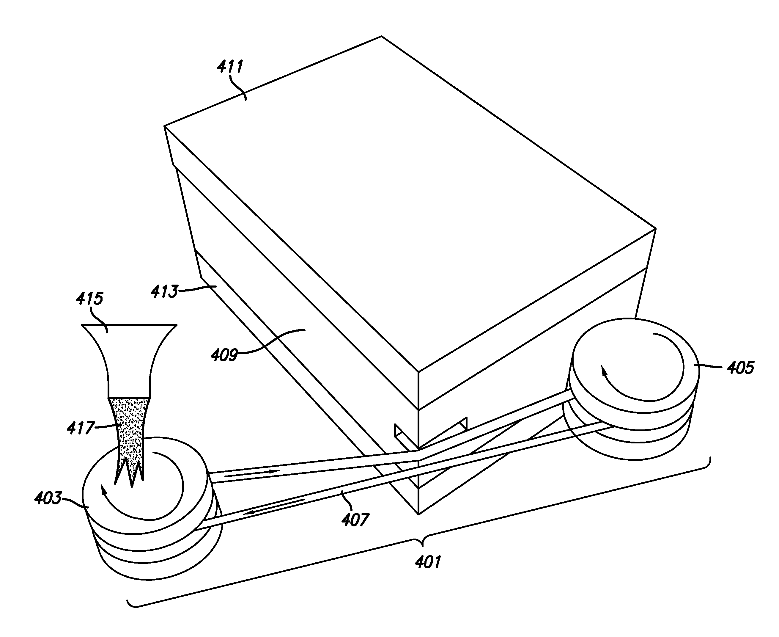
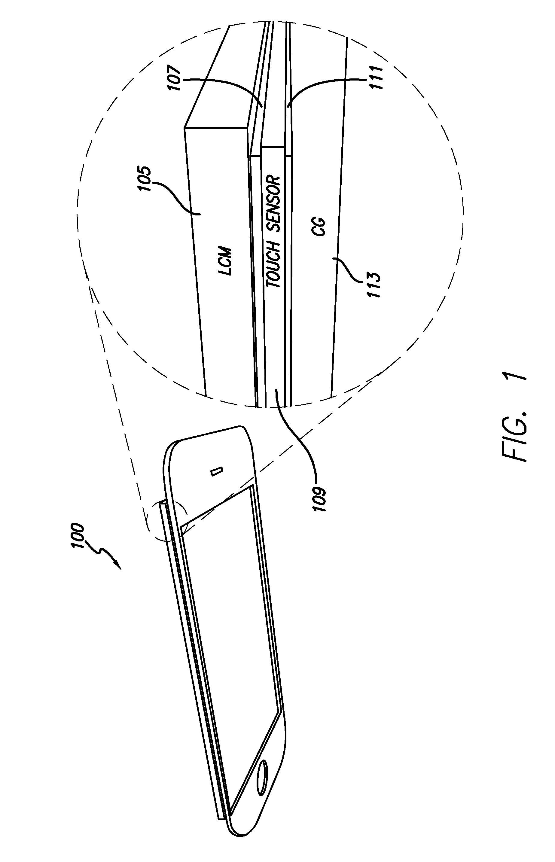
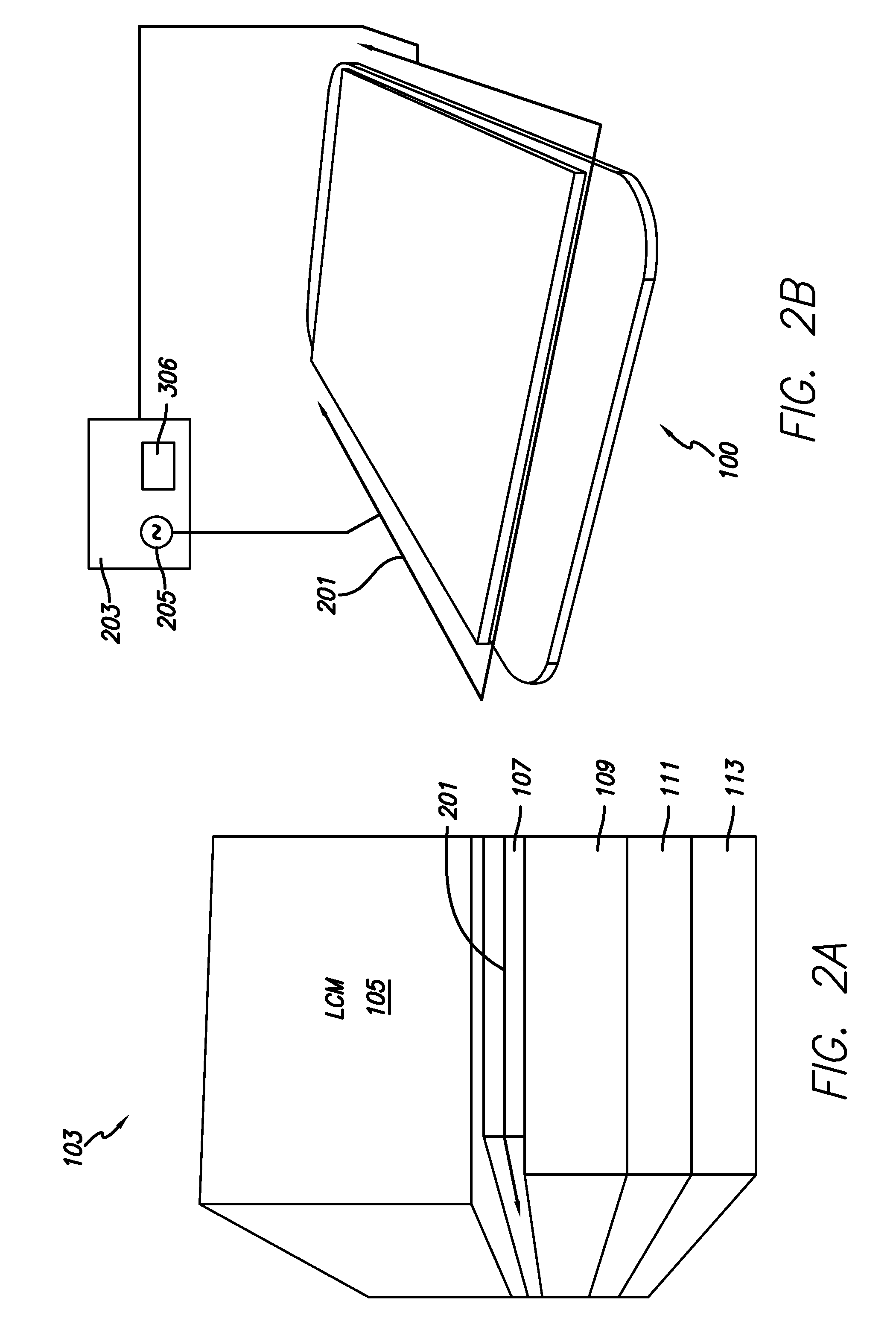
[0006]This relates to delaminating a laminated multilayer stack, and in particular, to weakening a bonding layer of a laminated multilayer stack by generating a layer-specific energy distribution in the stack during delamination. A layer-specific energy distribution can result from localized heating, cooling, or other form of energy absorption or transmission, in a bonding layer of a multilayer stack. A localized heating, for example, of a bonding layer can result in an increase of the temperature of the bonding layer to exceed a threshold temperature at which the bonding layer is weakened. Weakening the bonding layer can allow a faster and more efficient delamination process to separate layers held together by the bonding layer. Limiting the temperature increase, in this example, to the bonding layer can reduce or eliminate damage to other layers of the stack.

Problems solved by technology

Because of the strength and structural integrity of multilayer laminates, conventional delamination processes typically result in the destruction or degradation of one or more layers of a laminate.
However, in other applications the temperature increase may cause enough damage to the surrounding layers to render the layers partially or completely unusable.
Delamination by heating a multilayer laminate stack used in a typical LCD touch screen application, for example, is likely to destroy the touch screen's LCD functionality, although the resulting delaminated layers might still be usable in some types of failure analysis.

Method used


Image

  • Layer-specific energy distribution delamination
  • Layer-specific energy distribution delamination
  • Layer-specific energy distribution delamination

Examples


Embodiment Construction

[0021]In the following description, reference is made to the accompanying drawings which form a part hereof, and in which it is shown by way of illustration specific example embodiments in which the invention can be practiced. It is to be understood that other embodiments can be used and structural changes can be made without departing from the scope of the invention.

[0022]This relates to delaminating a laminated multilayer stack, and in particular, to weakening a bonding layer of a laminated multilayer stack by generating a layer-specific energy distribution in the stack during delamination. A layer-specific energy distribution can result from localized heating, cooling, or other form of energy absorption or transmission, in a bonding layer of a multilayer stack. A localized heating, for example, of a bonding layer can result in an increase of the temperature of the bonding layer to exceed a threshold temperature at which the bonding layer is weakened. Weakening the bonding layer c...


PUM

PropertyMeasurementUnit
temperatureaaaaaaaaaa
concentrationaaaaaaaaaa
thermal energyaaaaaaaaaa

Abstract

Delamination of a laminated multilayer stack is provided by generating a layer-specific energy distribution in the stack during delamination. A localized energy transferrer can generate localized heating, cooling heating, cooling, or other form of energy absorption or transmission, in a bonding layer of a multilayer stack. Localized energy transfer can include thermal energy transfer, such as heating and / or cooling, acoustic energy transfer, such as applying ultrasonic energy, electromagnetic energy transfer, such as applying laser light, directed microwaves, etc. Localized energy transfer can generate a layer-specific energy distribution that can weaken the bonding layer while reducing damage to other layers of the stack.

Description

[0001]This application claims the benefit of U.S. Provisional Application No. 61 / 140,072, filed Dec. 22, 2008, the contents of which are incorporated by reference herein.FIELD OF THE INVENTION[0002]This relates generally to delaminating a laminated multilayer stack, and in particular, to weakening a bonding layer of a laminated multilayer stack by generating a layer-specific energy distribution in the stack during delamination.BACKGROUND OF THE INVENTION[0003]Multilayer laminates have found use in a wide variety of applications, from exploratory space vehicles to consumer products. Many of these applications rely on the exceptional strength and structural integrity that multilayer laminates can provide.[0004]Because of the strength and structural integrity of multilayer laminates, conventional delamination processes typically result in the destruction or degradation of one or more layers of a laminate. One conventional delamination process, for example, is directed to multilayer lam...

Claims


Application Information

Patent Timeline
Patent Type & Authority Patents(United States)
IPC IPC(8): B29C63/00B32B7/12B32B37/16B32B38/16B23K26/00G06F3/0354G02F1/1333G02F1/13B26D3/28B26D1/547B26D7/10B32B43/00B23K26/06B32B38/00B26D7/08B26D1/00B32B37/18B32B38/04B32B37/12
CPCB32B38/0004B32B43/006B23K26/06B23K26/0604B32B37/16B32B38/16B23K26/00B23K26/0054G02F1/1309G06F3/03547B26D1/547G02F1/133308B26D3/28B23K26/0063G02F1/13338B32B7/12B26D7/10B32B37/12B32B2310/022B32B2310/0843B32B2457/20B32B2038/045B32B37/18B32B2310/028Y10T156/1911Y10T156/1184Y10T156/1158Y10T156/1917Y10T156/1153Y10T156/1967B32B2310/0862B32B2310/0806B32B2310/0825G06F2200/1634B26D3/282G06F2200/1635B26D2001/006B26D7/086B26D2001/0013B23K26/50B23K26/57
Inventor FEINSTEIN, CASEY J.GRESPAN, SILVIOSUNG, KUO-HUAZHONG, JOHN Z.YOUNGS, LYNN
Owner APPLE INC
Learn More