
Method of plasma-enhanced atomic layer etching

Active Publication Date: 2016-07-19
ASM IP HLDG BV
View PDF12 Cites 305 Cited by
  • Summary
  • Abstract
  • Description
  • Claims
  • Application Information

AI Technical Summary

Benefits of technology

This patent describes a method for atomic level etching that has several technical features. First, an etching gas and an inert gas are supplied to the reaction space in a way that increases purging efficiency. Second, a plasma is used for etching, and the etching rate can be controlled by adding or reducing a reactant gas. Third, the process temperature is controlled at a specific temperature. Finally, directionality of etching can be controlled by selecting the type of reactant gas and etching conditions. Overall, this method allows for more efficient and controlled etching at atomic levels.

Problems solved by technology

However, conventional etching technology such as continuous etching using excited reaction species may be difficult to form fine, narrow convex-concave patterns and may cause defects of shape.
However, low etching rate, poor controllability over directionality of etching, or the like need to be improved.

Method used


Image

  • Method of plasma-enhanced atomic layer etching
  • Method of plasma-enhanced atomic layer etching
  • Method of plasma-enhanced atomic layer etching

Examples


example 13

[0055]The ALE process was performed according to Example 5 above, except that the feed time of etching gas was changed. FIG. 4 is a graph showing the relationship between etching rate per cycle (EPC) (nm / cycle) and etching gas feed time per cycle (seconds). As shown in FIG. 4, after the feed time reached 0.2 seconds, EPC was unchanged, indicating that self-limiting adsorption reaction process was conducted.

example 14

[0056]The ALE process was performed according to Example 5 above, except that the purge time upon feeding of the etching gas was changed. FIG. 5 is a graph showing the relationship between etching rate per cycle (EPC) (nm / cycle) and purge time per cycle (seconds). As shown in FIG. 5, after the purge time reached 0.5 seconds, EPC was unchanged, indicating chemisorption of the etching gas was conducted.


PUM


Abstract

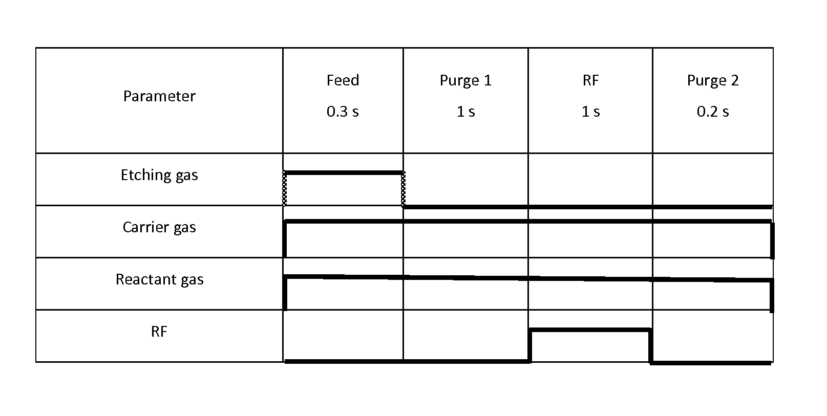
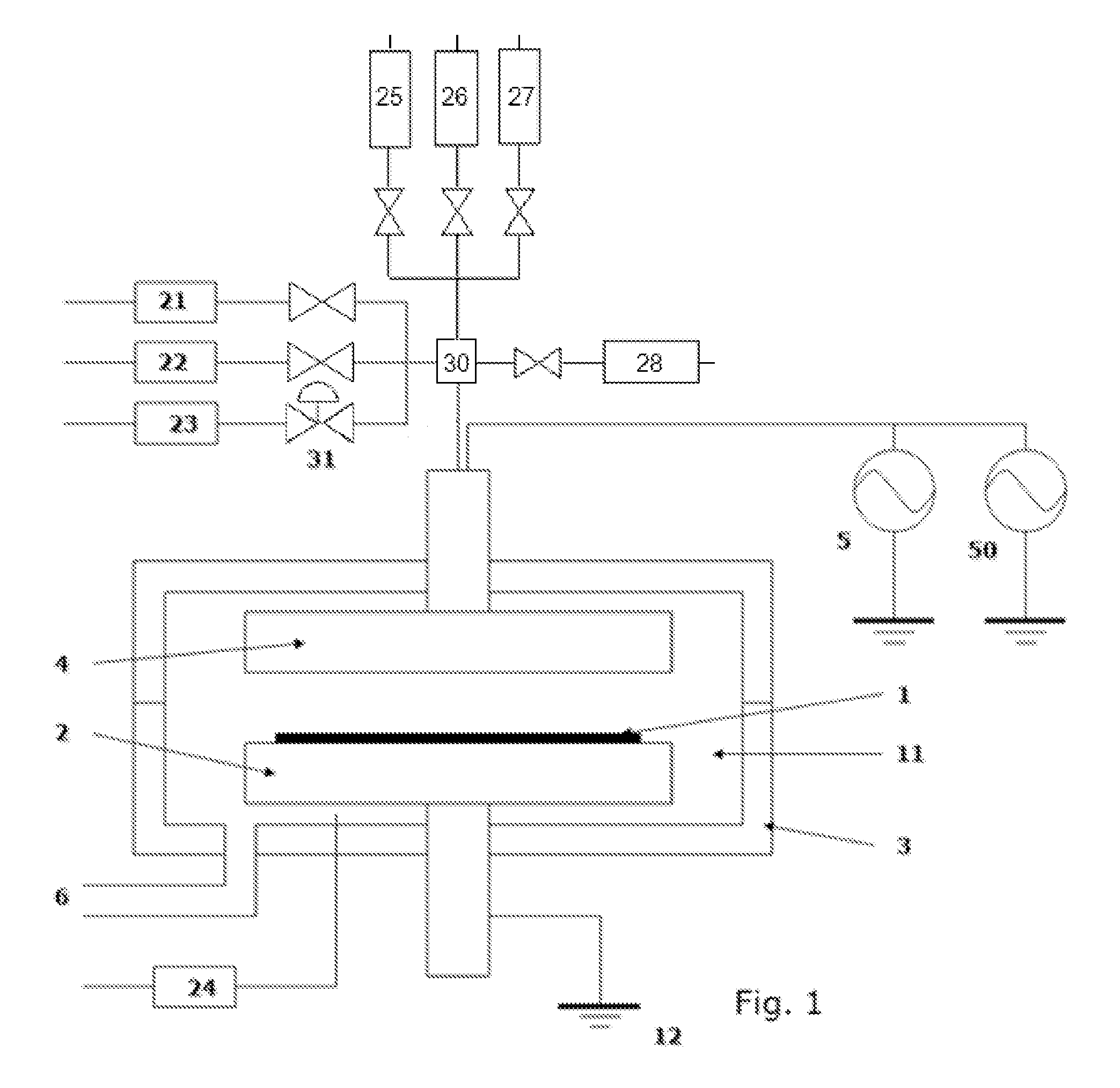
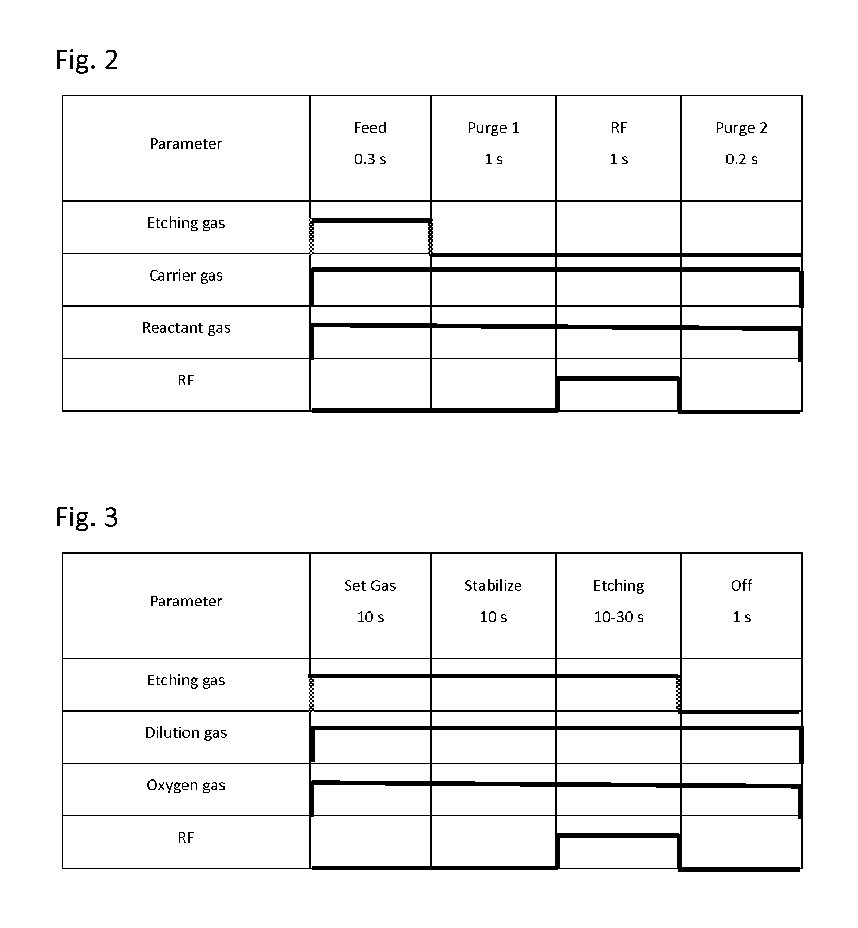
A method for etching a layer on a substrate includes at least one etching cycle, wherein an etching cycle includes: continuously providing an inert gas into the reaction space; providing a pulse of an etching gas into the continuous inert gas flow upstream of the reaction space to chemisorb the etching gas in an unexcited state on a surface of the substrate; and providing a pulse of RF power discharge between electrodes to generate a reactive species of the inert gas in the reaction space so that the layer on the substrate is etched.

Description

BACKGROUND OF THE INVENTION[0001]1. Field of the Invention[0002]The present invention generally relates to a method of atomic layer etching (ALE), particularly to a method of plasma-enhanced ALE (PEALE).[0003]2. Description of the Related Art[0004]In order to cope with various processing accompanying microminiaturization and complex structures of semiconductor devices, precision of processing has been remarkably improved by new technology such as double-patterning. However, conventional etching technology such as continuous etching using excited reaction species may be difficult to form fine, narrow convex-concave patterns and may cause defects of shape. Thus, development of etching technology which is capable of performing atomic layer-level etching and is suitable for e.g., double-patterning processes, becomes important. However, low etching rate, poor controllability over directionality of etching, or the like need to be improved.[0005]Any discussion of problems and solutions in ...

Claims


Application Information

Patent Timeline
IPC IPC(8): H01L21/3065H01L21/3213H01L21/67H01J37/32H01L21/311
CPCH01L21/31116H01L21/31111H01L21/67069H01J37/32146H01L21/3065H01L21/32137H01L21/32136H01J37/32449H01J37/32091
Inventor FUKAZAWA, ATSUKI
Owner ASM IP HLDG BV
Learn More