Magnetic component with auxiliary winding circuit board

a technology of auxiliary winding circuit board and magnetic component, which is applied in the direction of transformer/inductance details, coils, electrical devices, etc., can solve the problems of unsatisfactory performance, noise, magnetic coupling and efficiency loss, winding placement, etc., and achieves the effect of reducing the overall size of the component, reducing winding time, and reducing cos

Inactive Publication Date: 2016-07-19
UNIVERSAL LIGHTING TECHNOLOGIES
View PDF7 Cites 6 Cited by
  • Summary
  • Abstract
  • Description
  • Claims
  • Application Information

AI Technical Summary

Benefits of technology

[0015]A further object of the present invention is to provide a magnetic component with main and auxiliary windings on one component to reduce the overall size of the component.
[0016]An additional object of the present invention is to provide a magnetic component with main and auxiliary windings where only the main winding needs to be wound on the bobbin, reducing winding time and reducing cost.
[0017]A further object of the present invention is to provide a magnetic component with physical separation between the high-voltage main winding and the low-voltage auxiliary windings to reduce the likelihood of high potential failures.
[0018]Yet another object of the present invention is to provide a magnetic component with improved voltage isolation between a main winding located on the bobbin and one or more auxiliary windings located on the auxiliary winding circuit board.

Problems solved by technology

However, voltage effects between the windings can cause undesirable performance such as noise, magnetic coupling and efficiency losses.
Another problem associated with multiple-winding magnetic components is winding placement.
Conventional winding configurations that place main and auxiliary windings about a single bobbin structure include winding tolerances that may lead to inconsistent placement of the windings relative to each other and relative to the bobbin.
This may lead to inconsistent magnetic coupling between the high-voltage main winding and the lower-voltage auxiliary windings, causing variance in performance between components.
Additional problems with multiple windings on a single bobbin structure include high potential failures between windings, especially in high voltage applications.
Such failures may lead to device malfunction and risk of fire.
However, conventional printed winding boards for magnetic devices are limited in the number of loops or turns that may be printed on the winding board substrate.
For this reason, conventional printed winding boards are generally limited to relatively low-voltage applications as compared to bobbin-wound magnetic components used for higher-voltage applications.

Method used


Image

  • Magnetic component with auxiliary winding circuit board
  • Magnetic component with auxiliary winding circuit board
  • Magnetic component with auxiliary winding circuit board

Examples


Embodiment Construction

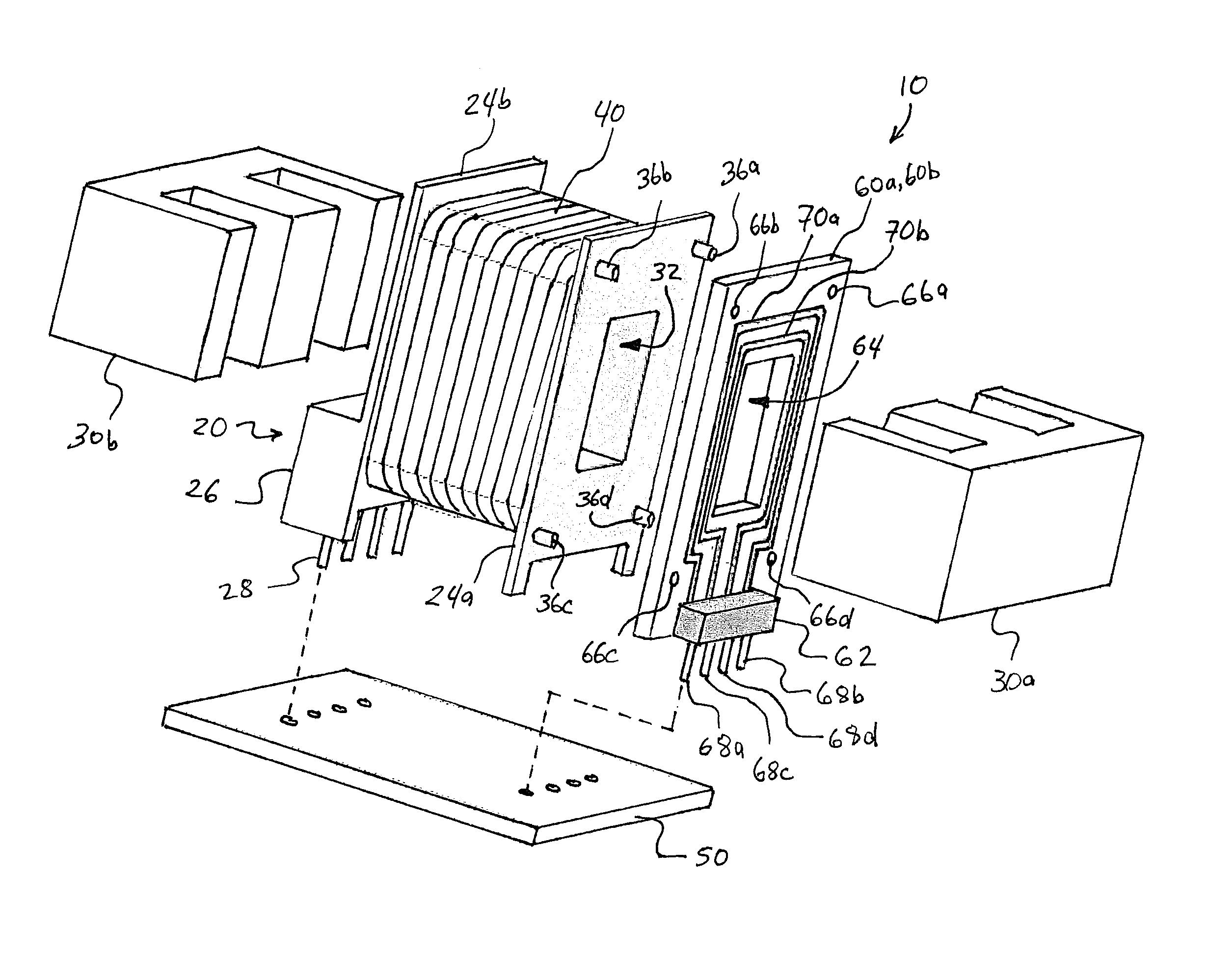
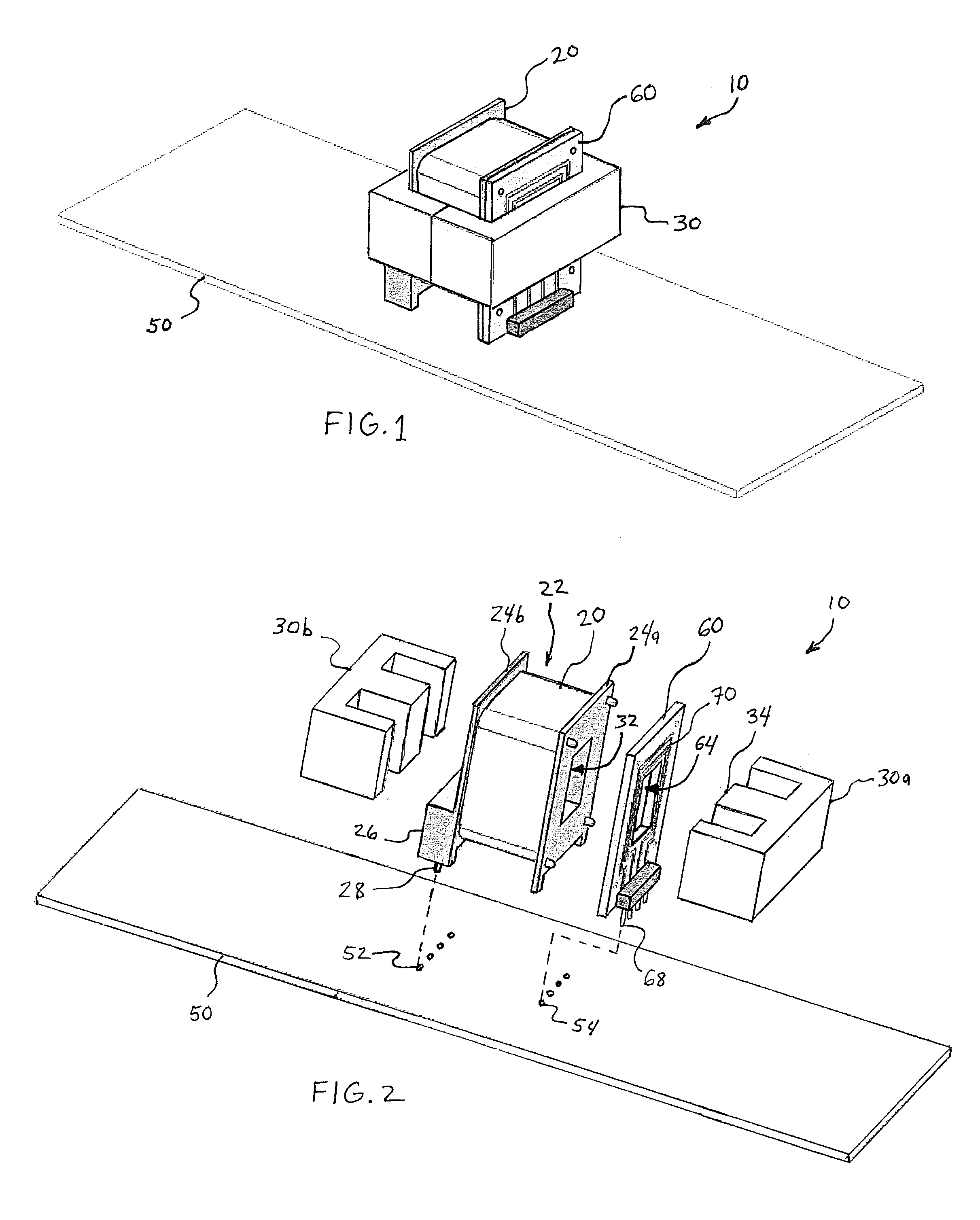
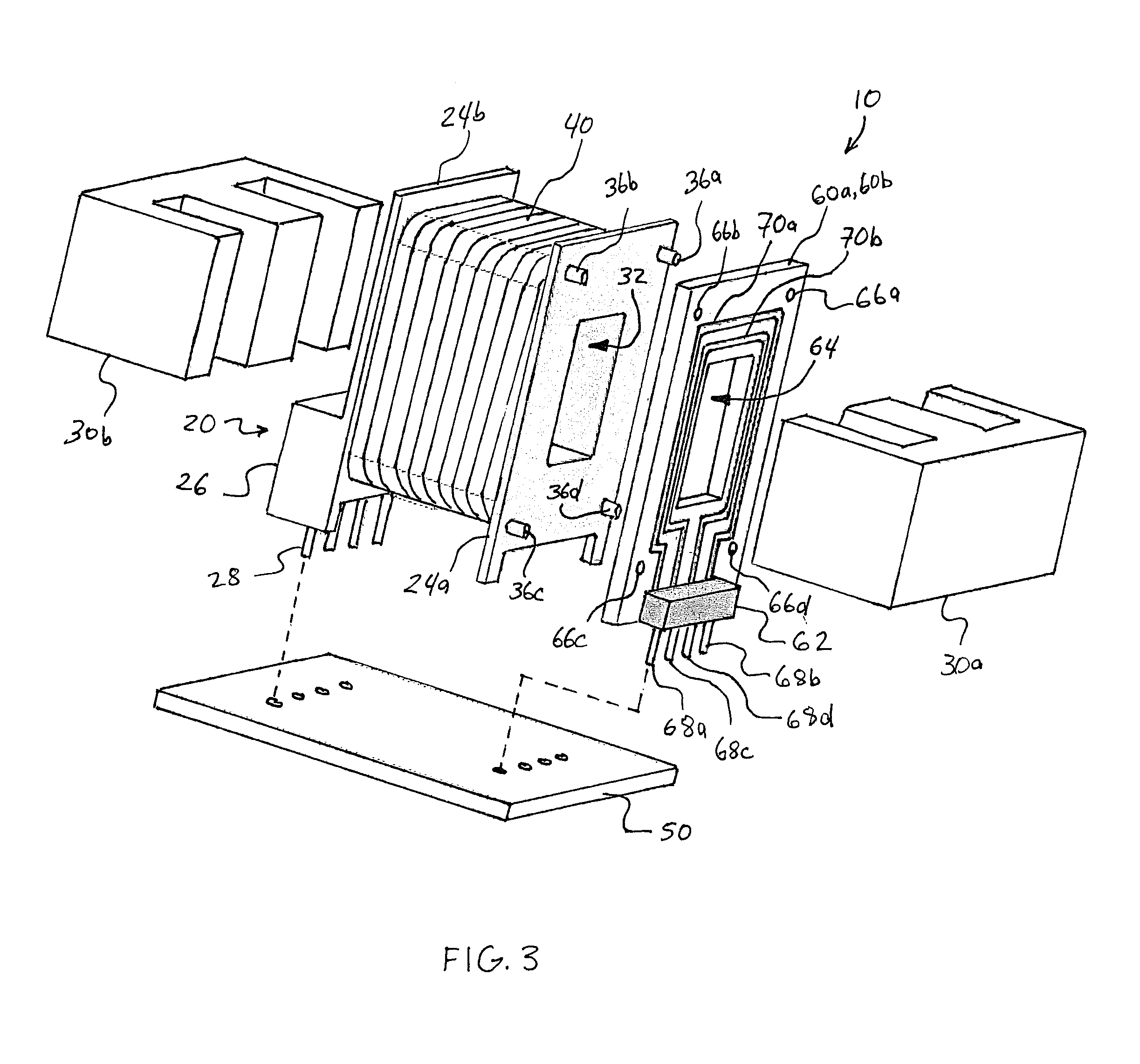
[0027]Referring now to the drawings, FIG. 1 illustrates an embodiment of a magnetic component apparatus 10 installed on a main printed circuit board 50. Magnetic component 10 may be a transformer and / or inductor in various embodiments. Magnetic component 10 generally includes a bobbin 20 and a magnetically permeable core 30. Core 30 in some embodiments is an E-core. Magnetic component 10 is generally installed on a main printed circuit board 50 having one or more circuits disposed thereon. In many applications, main printed circuit board 50 includes a circuit for a power supply or power converter device such as a lighting control, lighting ballast, AC / DC converter, or DC / DC converter. Magnetic component 10 is typically just one of several electronic components mounted on printed circuit board 50 in some embodiments. Other electronic components on main printed circuit board 50 may include resistors, capacitors, amplifiers, diodes, integrated circuits, transistors, and other component...


PUM

PropertyMeasurementUnit
conductiveaaaaaaaaaa
voltageaaaaaaaaaa
sizeaaaaaaaaaa

Abstract

An auxiliary winding circuit board includes one or more auxiliary conductive windings. The auxiliary winding circuit board is positioned at an axial end of a bobbin, and a core leg extends through an opening in the auxiliary winding circuit board. A main conductive winding is positioned on the bobbin. The auxiliary winding disposed on the auxiliary printed circuit board has enhanced voltage-isolation from the main winding positioned on the bobbin, allowing both a high-voltage main winding and a low-voltage auxiliary winding to be located on one magnetic component. The magnetic component is configured for mounting on a printed circuit board for an electronic device such as a power supply. A modular magnetic component apparatus includes a bobbin with main winding assembly and multiple auxiliary winding circuit boards that may be interchangeably mounted between the bobbin and core for desired applications.

Description

BACKGROUND OF THE INVENTION[0001]The present invention relates generally to magnetic component devices for electronic circuits, and more particularly to devices such as inductors and transformers for mounting on circuit boards.[0002]Conventional magnetic devices such as inductors and transformers typically include one or more conductive windings positioned about a bobbin or other winding spool. The windings may include primary and secondary windings in a transformer, or may include one or more windings in an inductor. Magnetic devices of this nature in some applications include multiple windings, or coils, positioned around the bobbin. Each winding includes one or more turns of a conductive wire covered with insulation around the bobbin. Conventional circuits for electronic applications such as power supplies and power converters, as well as other electronic components, often include high-voltage circuit regions and low-voltage circuit regions. In many applications it is desirable t...

Claims


Application Information

Patent Timeline
Patent Type & Authority Patents(United States)
IPC IPC(8): H01F27/30H01F27/28H01F27/29
CPCH01F27/2804H01F27/29H01F5/04H01F27/06H01F27/30H01F2005/043H01F2027/065
Inventor FOLKER, DONALDLEBLANC, MIKEBLEVINS, DAVID
Owner UNIVERSAL LIGHTING TECHNOLOGIES
Why Eureka
Try Eureka