Eureka AIR delivers breakthrough ideas for toughest innovation challenges, trusted by R&D personnel around the world.

Boom apparatus and concrete pump vehicle having same

a boom apparatus and concrete technology, applied in the field of construction machinery, can solve the problems of affecting the working efficiency of the concrete pump vehicle, the second boom cannot be unfolded simultaneously, and the boom apparatus is more time to unfold, so as to reduce the time required for unfolding and increase the maximum length of the unfolded boom apparatus

Inactive Publication Date: 2016-07-19
HUNAN SANY INTELLIGENT CONTROL EQUIP +1
View PDF10 Cites 5 Cited by
  • Summary
  • Abstract
  • Description
  • Claims
  • Application Information

AI Technical Summary

Benefits of technology

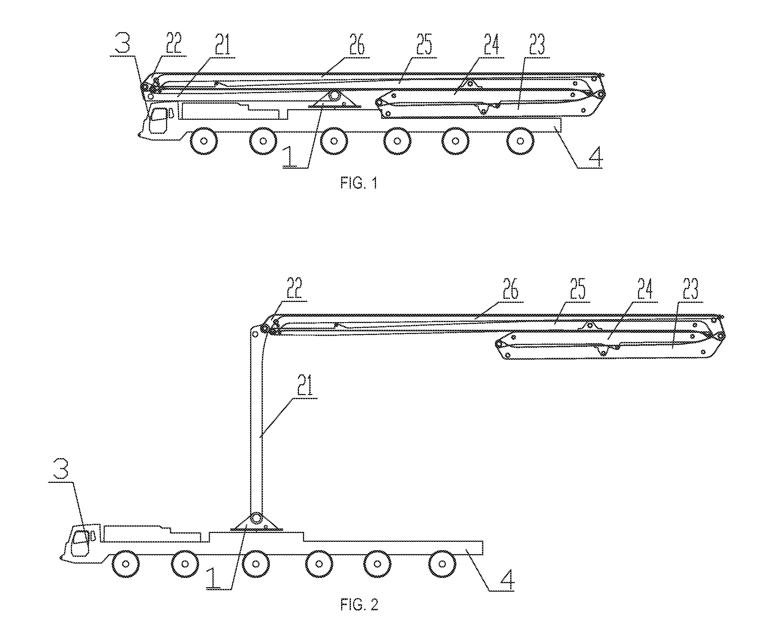
[0010]One of the objectives is to provide a boom apparatus, so as to solve the foregoing technical problems of the prior art. According to a structural design of the boom apparatus of the invention, a first boom and a second boom are enabled to be unfolded simultaneously, so as to reduce time required to unfold the boom apparatus. Further, the center of gravity of the vehicle is enabled to move forwards, so as to fully take advantage of axle loading capacity of the front axle. Furthermore, the last two booms of the boom apparatus can be extended, so as to increase a maximum length of the boom apparatus. Additionally, the invention also provides a concrete pump vehicle including the boom apparatus.
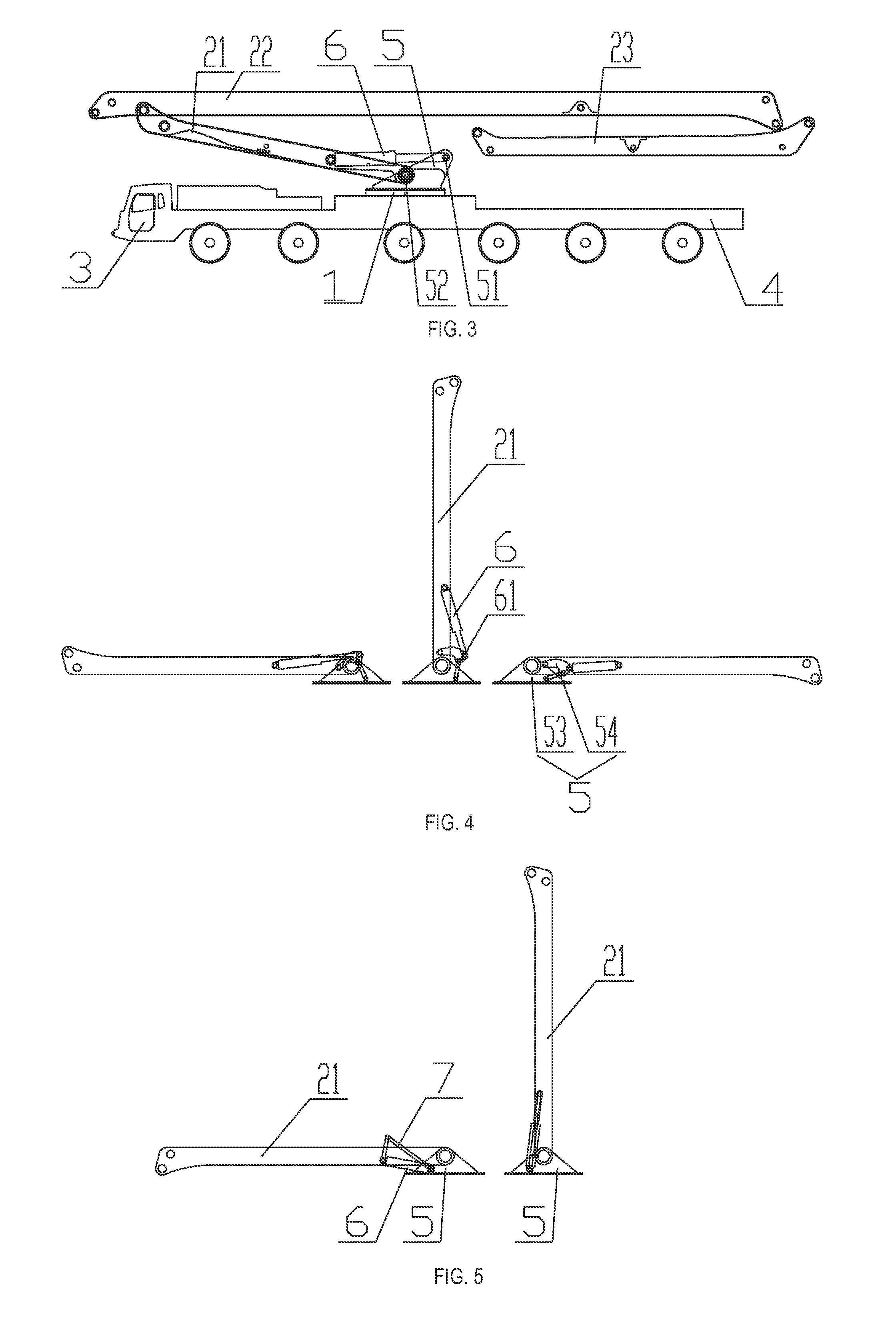
[0020]In one embodiment, the hinge-connecting plate includes a primary hinge-connecting plate and a secondary hinge-connecting plate. The first boom is hinge-connected to the primary hinge-connecting plate, a lower end of the first boom is hinge-connected to the secondary hinge-connecting plate, the derricking cylinder has one end hinge-connected to the first boom and the other end hinge-connected to the secondary hinge-connecting plate, and a connecting rod is further hinge-connected between the secondary hinge-connecting plate and the primary hinge-connecting plate, so that the first boom is capable of rotating by 180°.
[0023]Compared with the prior art, when the boom apparatus provided by the invention is in the folded state, the first boom is disposed on a side, close to the cab of the concrete pump vehicle, of the turntable, and the second boom is further hinge-connected above the first boom, so that the first boom and the second boom can be unfolded simultaneously, which avoids the problem of extended time incurred by non-simultaneous unfolding of the two, so as to reduce time required for unfolding the boom apparatus, thereby ensuring working efficiency of the concrete pump vehicle.
[0024]Additionally, the second boom and the first boom can be unfolded simultaneously, and as unfolding continues, the second boom is increasingly farther away from a boarding platform, so that last two booms, which move along with the second boom, can be made longer without worrying about the problem that when the first boom and the second boom are unfolded, the last two booms hit the boarding platform, thereby increasing the maximum length of the unfolded boom apparatus.
[0025]Further, the first boom is disposed on the side, close to the cab of the concrete pump vehicle, of the turntable, and the second boom and the last two boom are also partially disposed on the side, close to the cab of the concrete pump vehicle, of the turntable, so that the center of gravity of the vehicle can be moved forwards, so as to fully take advantage of axle loading capacity of the front axle of the concrete pump vehicle, thereby making the position of the center of gravity reasonable.

Problems solved by technology

However, the concrete pump vehicle disclosed in the PCT Publication has the following defects.
Firstly, the first boom and the second boom cannot be unfolded simultaneously.
Therefore, it takes the boom apparatus more time to unfold completely, thereby affecting working efficiency of the concrete pump vehicle.
Secondly, the seven booms are all disposed backwards, and located on the side, close to the rear of the vehicle, of the turntable, so that the space from one side, close to the cab, of the turntable to the position above the cab is not utilized, and a maximum length of the unfolded boom apparatus is also limited.
Thirdly, the seven booms are all disposed backwards, and located on the side, close to the rear of the vehicle, of the turntable, so that the position of the center of gravity of the vehicle is close to the rear, the position of the center of gravity is not reasonable, and axle loading capacity of the front axle of the concrete pump vehicle is not fully taken advantage thereof.
Therefore, a heretofore unaddressed need exists in the art to address the aforementioned deficiencies and inadequacies.

Method used


Image

  • Boom apparatus and concrete pump vehicle having same
  • Boom apparatus and concrete pump vehicle having same
  • Boom apparatus and concrete pump vehicle having same

Examples


Embodiment Construction

[0033]The invention will now be described more fully hereinafter with reference to the accompanying drawings, in which exemplary embodiments of the invention are shown. This invention may, however, be embodied in many different forms and should not be construed as limited to the embodiments set forth herein. Rather, these embodiments are provided so that this disclosure will be thorough and complete, and will fully convey the scope of the invention to those skilled in the art. Like reference numerals refer to like elements throughout.

[0034]It will be understood that when an element is referred to as being “on” another element, it can be directly on the other element or intervening elements may be present therebetween. In contrast, when an element is referred to as being “directly on” another element, there are no intervening elements present. As used herein, the term “and / or” includes any and all combinations of one or more of the associated listed items.

[0035]It will be understood ...


PUM


Abstract

In one aspect of the invention, a boom apparatus used for a concrete pump vehicle includes multiple booms, where the multiple booms comprise a first boom hinge-connected to a turntable of the concrete pump vehicle and a second boom hinge-connected to the first boom. When the boom apparatus is in a folded state, the first boom extends towards a cab of the concrete pump vehicle, and the second boom is further placed above the first boom. The invention also provides a concrete pump vehicle having the boom apparatus.

Description

CROSS-REFERENCE TO RELATED APPLICATIONS[0001]This application is a continuation application of International Patent Application No. PCT / CN2012 / 074113, filed Apr. 16, 2012, entitled “CONCRETE PUMP TRUCK AND ARM STAND DEVICE THEREOF”, by Xiaogang Yi et al., which itself claims the priority to Chinese Patent Application No. 201110240476.9, filed Aug. 19, 2011, entitled “BOOM APPARATUS AND CONCRETE PUMP VEHICLE HAVING SAME”, by Xiaogang Yi et al., the disclosures for which are hereby incorporated herein in their entireties by reference.FIELD OF THE INVENTION[0002]The invention relates to the field of construction machinery, and more particularly to a boom apparatus and a concrete pump vehicle having the boom apparatus.BACKGROUND OF THE INVENTION[0003]A concrete pump vehicle is common construction machinery and is used to deliver concrete slurry to a predetermined location through a delivery pipeline, so as to perform a concrete pouring operation in a location away from a mixing station....

Claims


Application Information

Patent Timeline
Patent Type & Authority Patents(United States)
IPC IPC(8): E03B1/00E04G21/04B66C23/00
CPCE04G21/0445B66C23/54E04G21/0436
Inventor YI, XIAOGANGXIE, SHIHUITAN, HAIBO
Owner HUNAN SANY INTELLIGENT CONTROL EQUIP
Why Eureka
Eureka Blog
Learn More