
Two sealant two phase wire connector

a sealing and two-phase technology, applied in the direction of coupling device connection, coupling device details, coupling base/case, etc., can solve the problems of varying time to failure, difficult to determine, and failures of either method of waterproofing

Active Publication Date: 2016-07-12
THE PATENT STORE
View PDF15 Cites 17 Cited by
  • Summary
  • Abstract
  • Description
  • Claims
  • Application Information

AI Technical Summary

Benefits of technology

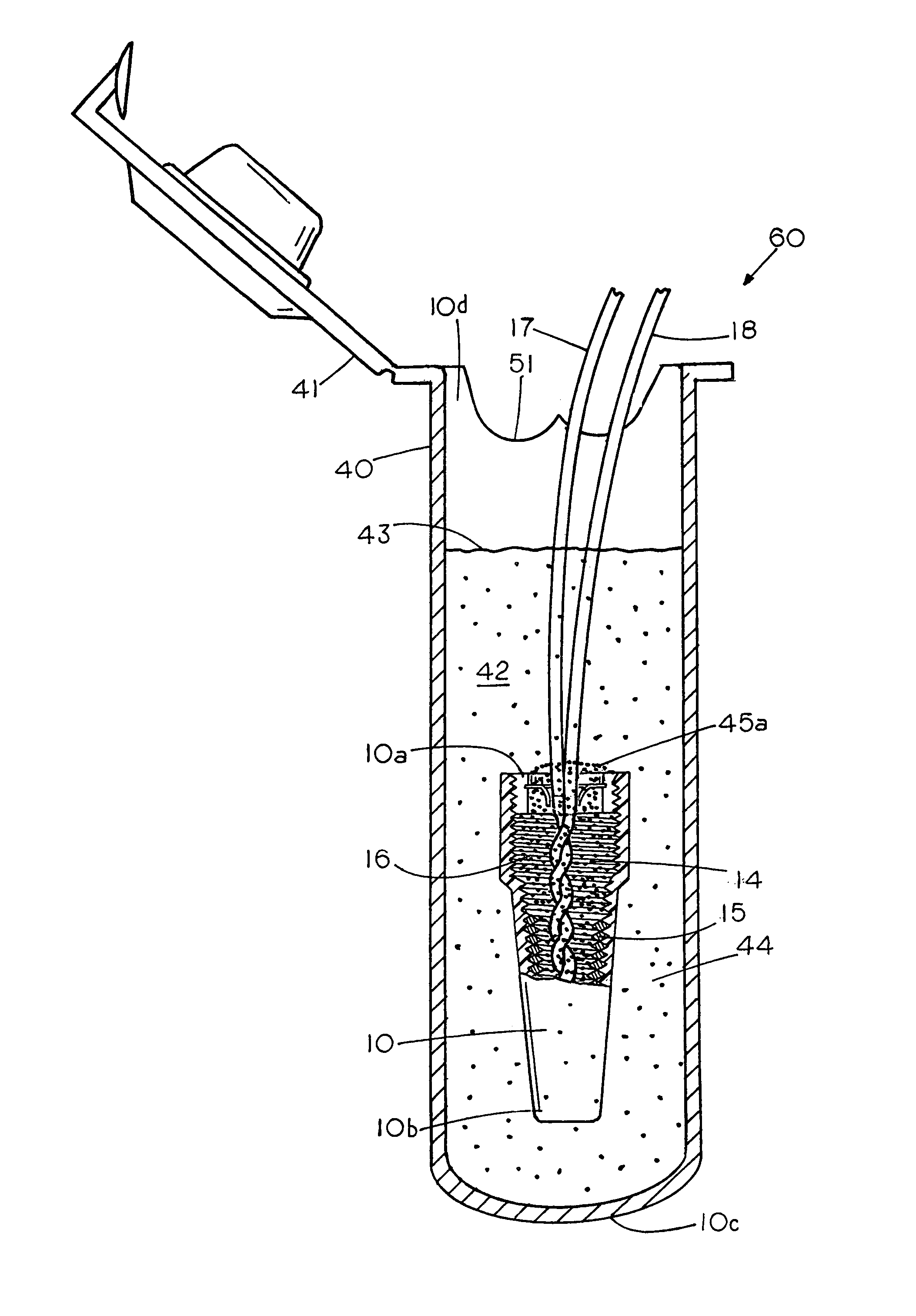
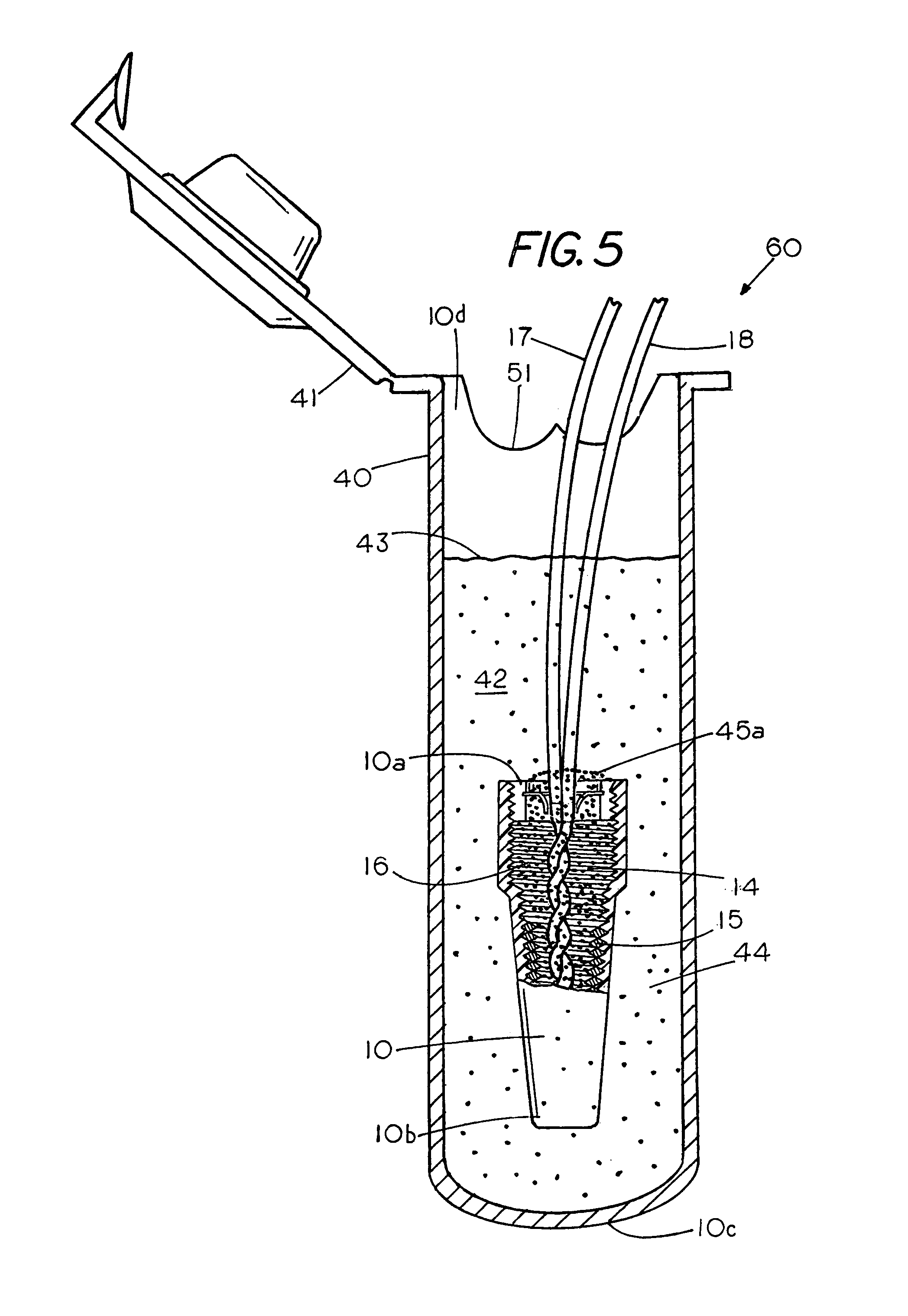
This patent describes a special connector for electrical wires that prevents electrical failures by using sealants. The connector has two parts: a sealant containing tube and a twist-on electrical wire connector. The wires are joined in the connector containing the sealant to form a first sealant / air interface. Then, the wires and connector are immersed in a tube containing a second sealant. The two sealants share and form a barrier to the environment, which prevents future electrical failures.

Problems solved by technology

Either method of waterproofing the electrical junction has been found to work well, however, failures have been known to occur with either method of waterproofing.
While such failures are rare the time to failure varies since the failure of electrical connections have been known to occur many months or even decades after the formation of the electrical connection.
While it difficult to determine the actual cause of the electrical failure there has been speculation that the failure of the electrical connection, which in some cases is due to exposure of a portion of the bared end of the electrical wires, may be due to human error in forming the electrical connection or human error in the immersion of the twist on wire connector in a body of sealant.
While the failure of twist-on wire connectors occurs in both the sealant filled wire connector and the sealant immersed wire connector the time of failure and location of the failure makes is difficult to diagnose the events that lead to the failure of the electrical connection.
Consequently, conditions exist where waterproof twist-on wire connectors, which have a viscous sealant for encapsulating the bared ends of an electrical wire, fail causing a short.
Likewise there exist conditions where the twist-on wire connectors, which are immersed in a sealant, also fail.
In either case the failures are extremely rare, however, the shear number of twist-on electrical wire connectors used at a work site and through the electrical industry increases the odds that an electrical connection may fail at a job site with the potential for disastrous results.

Method used


Image

  • Two sealant two phase wire connector
  • Two sealant two phase wire connector
  • Two sealant two phase wire connector

Examples


Embodiment Construction

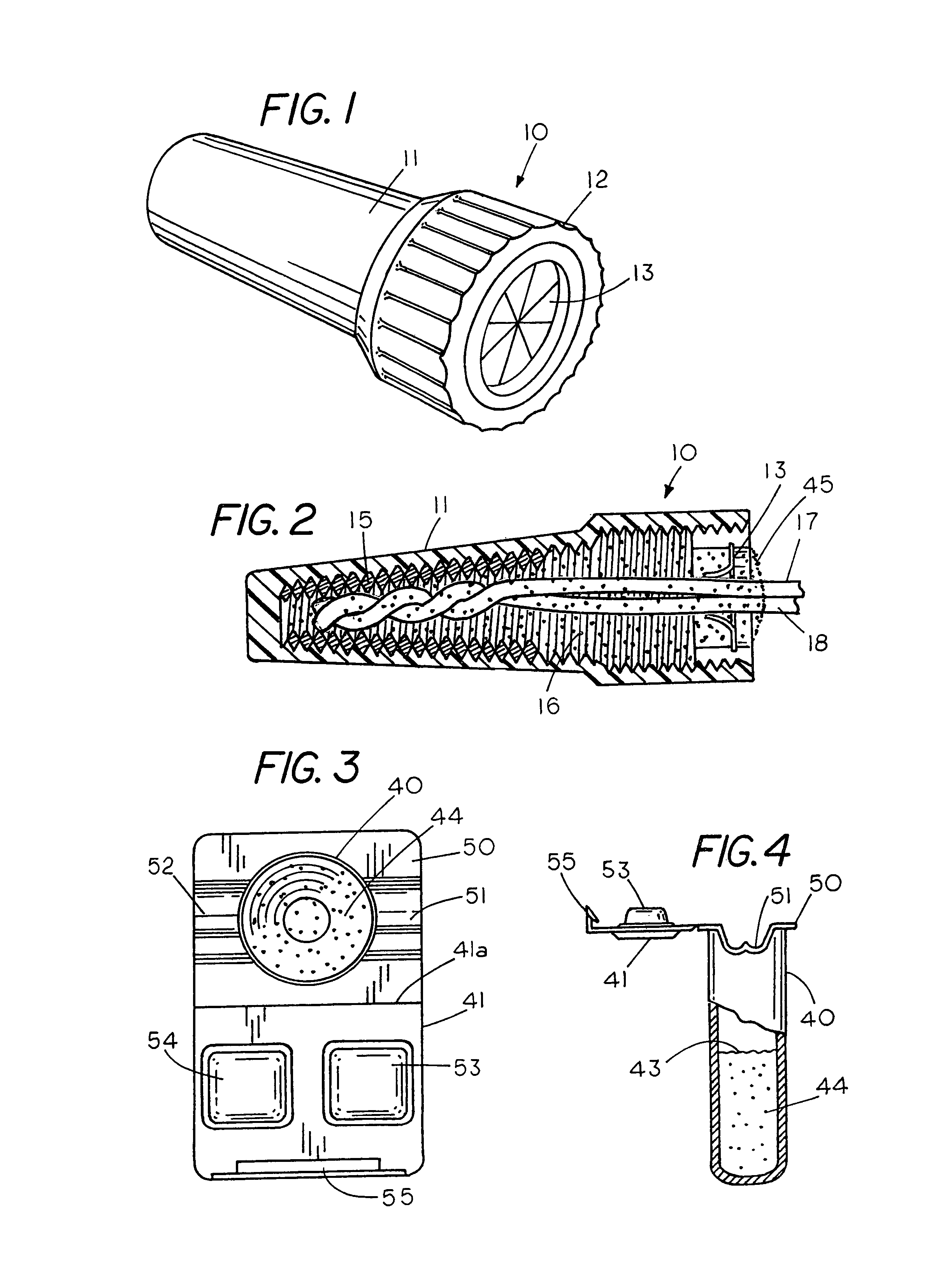
[0020]FIG. 1 is a perspective view of a twist-on wire connector 10 containing a water-resistant sealant with twist-on wire connector 10 having an outer electrically insulating shell 11 and a base 12 with a peripheral band of ridges 10a for grasping between the user's thumb and fingers. A pierceable cover 13 comprising a set of pie shaped flexible segments 13a extends over the open end of the connector 10. The flexible segments flex in response to axial wire pressure to enable a person to insert electrical wires into the interior of the twist-on wire connector and into twisted engagement with each other in a chamber in the interior of the twist-on wire connector 10.

[0021]FIG. 2 shows a sectional view of the twist-on wire connector 10 of FIG. 1 revealing an interior spiral coil 15 and a sealant 16 located in a chamber 14 within the twist-on wire connector 10. A pair of electrical wires 17 and 18 having bared ends 17a and 18a are shown electrical joined to each other in the presence of...


PUM


Abstract

A two sealant two-phase wire connector having sequential sealant interfaces for preventing an electrical failure through interactive sealant sharing between a twist-on electrical wire connector having a spiral cavity containing a first waterproof sealant which is immersed in a tube that contains a second water proof sealant, wherein the first water proof sealant and the second water proof sealant each form an interface that shields an electrical connection from the environment.

Description

CROSS REFERENCE TO RELATED APPLICATIONS[0001]NoneSTATEMENT REGARDING FEDERALLY SPONSORED RESEARCH OR DEVELOPMENT[0002]NoneREFERENCE TO A MICROFICHE APPENDIX[0003]NoneBACKGROUND OF THE INVENTION[0004]The use of twist-on electrical wire connectors in areas that may be wet or exposed to moisture requires the bared ends of the electrical wires, which are mechanically joined through a twisting action, to be protected from exposure to moisture, not only immediately after formation of the electrical connection but in some cases for years or decades after formation of the electrical connection. Compounding the problem of waterproofing an electrical wire connection and in particularly a twist-on wire connector where the electrical wire connection may have to last for decades are the conditions existing during the formation of the electrical connection. Typically, an electrical wire connection is formed on-the-go and in the field where the field conditions and the environment may be adverse t...

Claims


Application Information

Patent Timeline
IPC IPC(8): H01R4/00H01R13/52H01R43/20H01R4/22
CPCH01R13/52H01R43/20H01R4/22H01R13/5216H01R13/5205
Inventor KING, JR., L. HERBERTJAMES, PAUL
Owner THE PATENT STORE
Learn More