Receptacle assembly and set of receptacle assemblies for a communication system

a technology of a communication system and a receptacle assembly, which is applied in the direction of coupling device connection, optical elements, instruments, etc., can solve the problems of inability to use conventional receptacle assemblies, inability to meet the requirements of heat transfer, and inability to reliably and electrically perform modules/systems

Active Publication Date: 2016-07-12
TYCO ELECTRONICS LOGISTICS AG (CH)
View PDF11 Cites 54 Cited by
  • Summary
  • Abstract
  • Description
  • Claims
  • Application Information

AI Technical Summary

Benefits of technology

The patent is for a receptacle assembly that can hold different types of pluggable modules. The assembly includes a housing with a special area for locating the modules and a communication connector that can be used with both finned and un-finned pluggable modules. The special module cavity is designed to hold both types of modules and ensure they are properly positioned. The technical effect of this invention is to provide flexibility and versatility in the design of a receptacle assembly, allowing it to accommodate different types of pluggable modules and ensuring proper positioning and engagement with the network.

Problems solved by technology

A challenge often encountered in the design of the pluggable module and receptacle assembly is the heat generated during operation of the communication system, which negatively affects module / system reliability and electrical performance.
Conventional designs are proving to be inadequate for the required heat transfer leading to design of newer pluggable modules having heat fins built into the pluggable modules.
Such pluggable modules are typically thicker and are unable to be used with conventional receptacle assemblies due to the size and shape of the pluggable modules with fins.
As such, some pluggable modules are unusable with some receptacle assemblies leading manufacturers of communication systems to pick one particular type of module and / or receptacle assembly.

Method used


Image

  • Receptacle assembly and set of receptacle assemblies for a communication system
  • Receptacle assembly and set of receptacle assemblies for a communication system
  • Receptacle assembly and set of receptacle assemblies for a communication system

Examples


Embodiment Construction

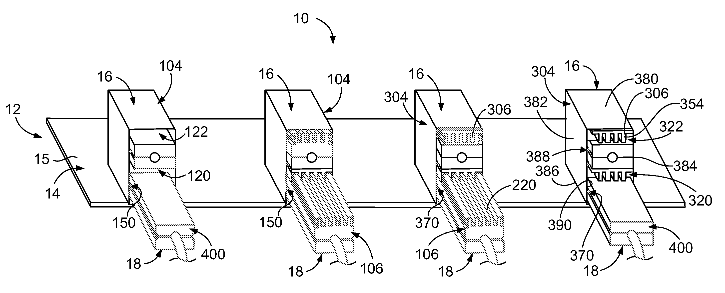
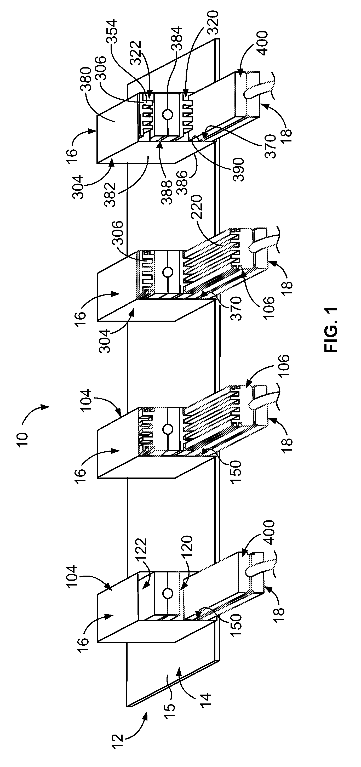
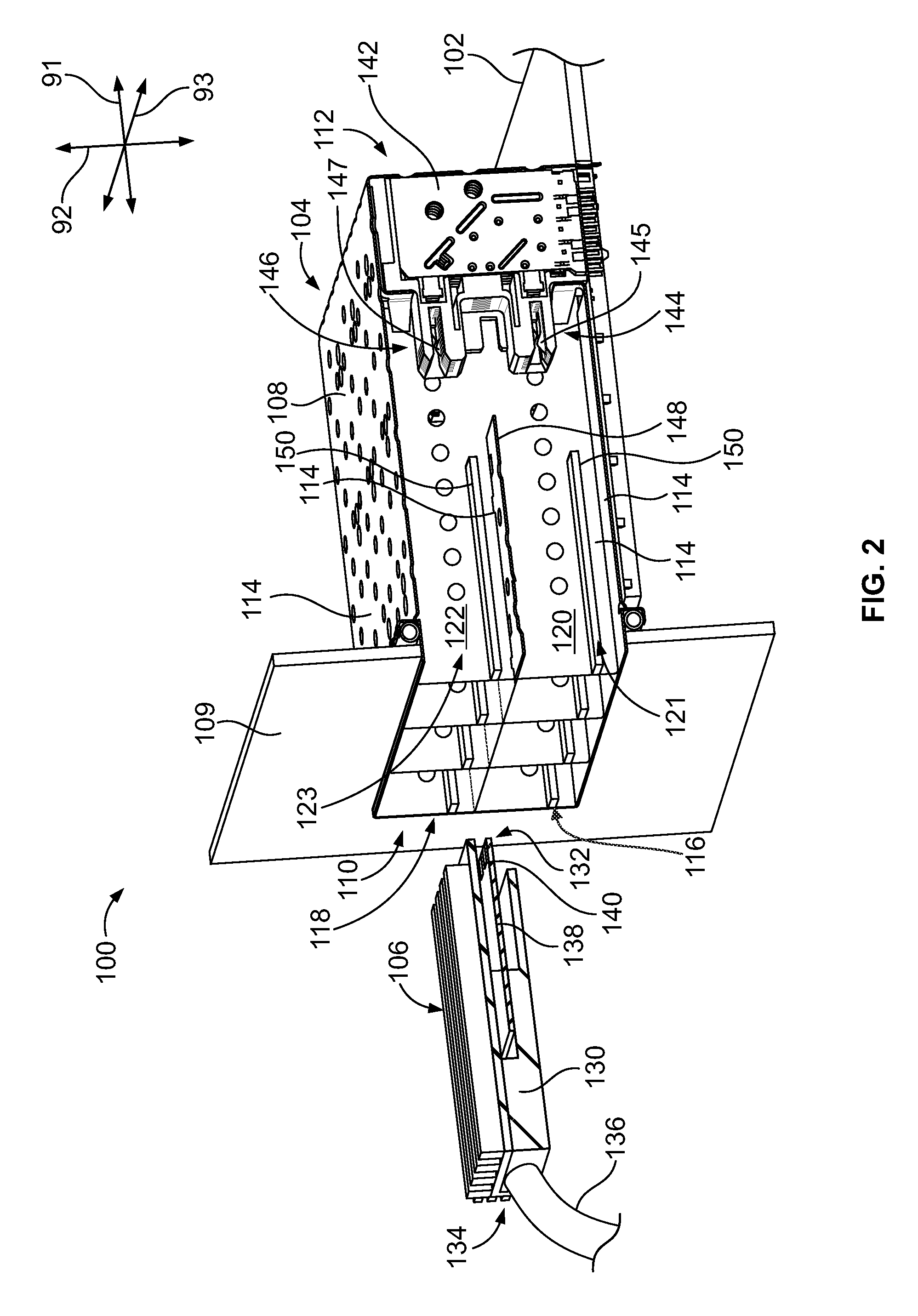
[0020]Embodiments set forth herein include communication systems including a family of connectors that are interoperable and interconnectable. The communication system includes sets of receptacle assemblies and sets of pluggable modules that are interoperable. For example, the communication system may include a set of two or more different types of receptacle assemblies. The communication system may include a set of two or more different types of pluggable modules.

[0021]Various embodiments described herein include receptacle assemblies having different characteristics or features, but each of the receptacle assemblies is able to receive the different types of pluggable modules therein. Similarly, the pluggable modules have different characteristics or features, but each of the pluggable modules is configured to be received in each of the various types of receptacle assemblies. For example, in an exemplary embodiment, the communication system includes both finned pluggable modules ha...


PUM


Abstract

A receptacle assembly includes a receptacle housing having a module cavity with communication connector positioned in the receptacle housing. The module cavity is oversized to selectively receive a finned pluggable module having a plurality of heat transfer fins and is configured to selectively receive an un-finned pluggable module having a thickness dimension that is smaller than a thickness dimension of the finned pluggable module. The mating interface of the communication connector being selectively matable with both the finned pluggable module and the un-finned pluggable module. Locating features being configured to engage and locate both the finned pluggable module and the un-finned pluggable module depending on which of the finned pluggable module or the un-finned pluggable module is loaded into the module cavity.

Description

BACKGROUND OF THE INVENTION[0001]The subject matter described herein relates to a receptacle assembly that receives a pluggable module in a communication system.[0002]At least some known communication systems include receptacle assemblies, such as input / output (I / O) connector assemblies, that are configured to receive a pluggable module and establish a communicative connection between the pluggable module and an electrical connector of the receptacle assembly. As one example, a known receptacle assembly includes a receptacle housing that is mounted to a circuit board and configured to receive a small form-factor (SFP) pluggable transceiver. The receptacle assembly includes an elongated cavity that extends between an opening of the cavity and an electrical connector that is disposed within the cavity and mounted to the circuit board. The pluggable module is inserted through the opening and advanced toward the electrical connector in the cavity. The pluggable module and the electrical...

Claims


Application Information

Patent Timeline
IPC IPC(8): G02B6/36H01R12/70G02B6/38H01R27/02
CPCG02B6/3814H01R12/7076H01R27/02G02B6/3825G02B6/3831H01R12/71H01R13/502H01R12/722H01R13/659H01R13/6594H01R13/6587H01R27/00G02B6/4269G02B6/4284
Inventor SHARF, ALEX MICHAEL
Owner TYCO ELECTRONICS LOGISTICS AG (CH)
Why Eureka
Try Eureka