
Cash box with a height limiter engaging with the retaining element

a technology of height limiter and retaining element, which is applied in the field of cash boxes, can solve the problems of difficult automatic filling of cash boxes, and achieve the effect of sufficient force and simple construction

Active Publication Date: 2016-07-12
DIEBOLD NIXDORF SYST GMBH
View PDF11 Cites 8 Cited by
  • Summary
  • Abstract
  • Description
  • Claims
  • Application Information

AI Technical Summary

Benefits of technology

[0009]Due to the fact that only the height limiter mounted to the cover is provided and the lateral height limiters can be dispensed with, it is achieved that, when the cover is open, a value note stack can be fed in a straight line through the first opening without difficulty, and it is no longer necessary that this stack is moved laterally on the bottom unit. As only the one height limiter on the cover is provided, this limiter is completely removed when the cover is open and thus does not impede the feeding of notes of value to the receiving area.
[0027]In an alternative embodiment, the press-on unit may also only be as high as the planar area facing the box bottom so that the press-on unit reliably presses the notes of value against this planar area with sufficient force. This embodiment has the advantage that a projection on the press-on unit can be dispensed with and thus this press-on unit is constructed as simple as possible.

Problems solved by technology

These lateral height limiters, however, have the disadvantage that they make the automatic filling of the cash box more difficult since notes of value first have to be inserted laterally next to the lateral height limiters and then have to be moved under said limiters.
During this displacement of the notes of value, there is the risk that individual notes of value which slightly project from the value note stack might be pulled under the other notes of value of the stack which may result in problems during the subsequent withdrawal operation.

Method used


Image

  • Cash box with a height limiter engaging with the retaining element
  • Cash box with a height limiter engaging with the retaining element
  • Cash box with a height limiter engaging with the retaining element

Examples


Embodiment Construction

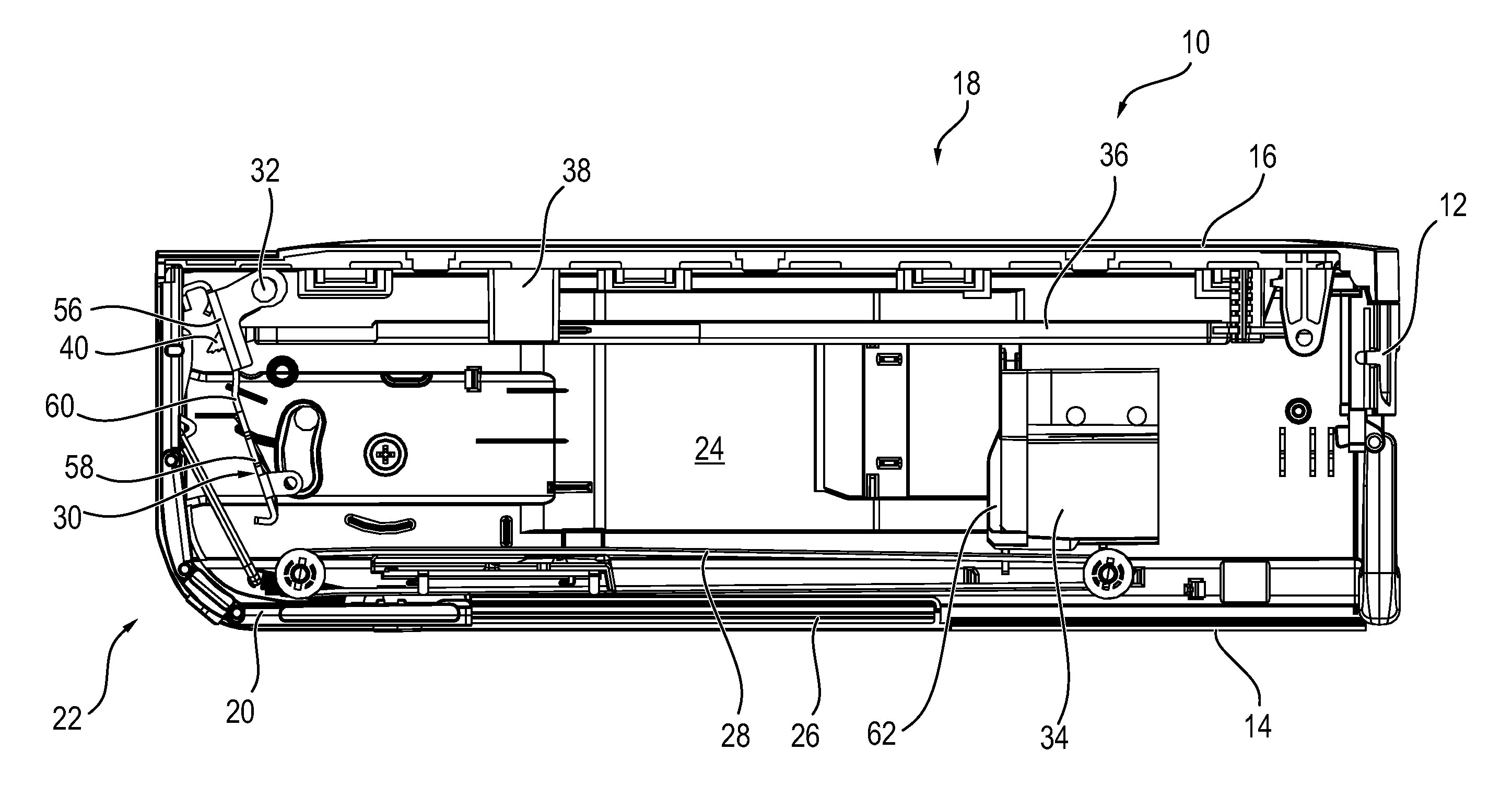
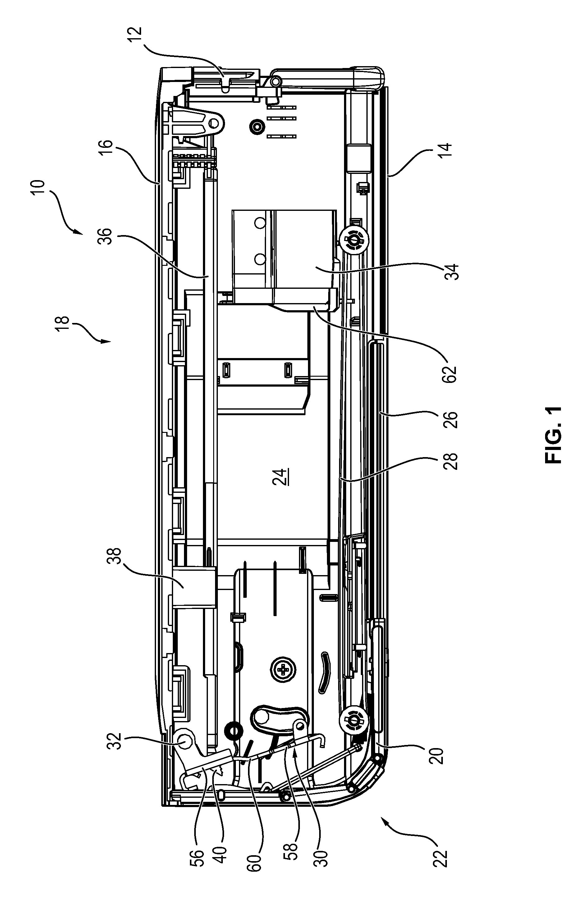
[0035]FIG. 1 is a schematic illustration of a cash box 10 according to a first embodiment, which comprises a housing 12 having a box bottom 14. The cash box 10 has a first opening 18 for manually feeding and / or removing notes of value, which first opening is closable by a cover 16, and a second opening 22 for automatically feeding of notes of value, which second opening is closable by a closing unit 20. The first opening 18 is in particular arranged at the top and the second opening 22 is arranged at one of the face sides of the cash box 10.

[0036]The receiving area 24 for receiving notes of value is delimited toward the box bottom 14 by a bottom unit 26 which in particular has several belts 28 on which the received notes of value stand on their edges.

[0037]Toward the second opening 22, the receiving area 24 is delimited by a retaining element 30 which is pivotable about an axis of rotation 32 between a retaining position shown in FIG. 1 and a feeding position shown in FIG. 2. In the...


PUM


Abstract

The invention relates to a cash box (10, 100, 102) comprising a receiving area (24) for receiving a value note stack and a first opening (18) for manually feeding and removing notes of value, which first opening is closable by a cover (16). On the cover (16), a height limiter (36) for adjusting the height of the receiving area (24) is provided, this height limiter (36) comprising at least one finger (40, 42) which, at least when the cover (16) is closed, projects into a recess (44, 46) of a retaining element (30).

Description

CROSS REFERENCE TO RELATED APPLICATIONS[0001]This application claims the benefit and priority of European Patent Application No. EP 14 157 344.4 filed Feb. 28, 2014. The entire disclosure of the above application is incorporated herein by reference.BACKGROUND[0002]1. Technical Field[0003]The invention relates to a cash box comprising a receiving area for receiving a value note stack and a first opening for manually feeding and / or removing notes of value to and from the receiving area, respectively, which first opening is closable by a cover. Further, the cash box has a bottom unit which delimits the receiving area toward a box bottom and a retaining element which, in a retaining position, retains the notes of value received in the receiving area in said receiving area and which, in a feeding position, enables a feeding and / or removing of the notes of value through a second opening for the automatic feeding and / or removing of notes of value. On the cover, a height limiter for adjusti...

Claims


Application Information

Patent Timeline
Patent Type & Authority Patents(United States)
IPC IPC(8): E05G1/00G07D11/00
CPCE05G1/005G07D11/0012G07D11/13
Inventor GEESMEIER, ANDREASHEIMANN, PETERWELTER, RALFVOSS, HANS-GUENTERLANGHUBER, DIRK
Owner DIEBOLD NIXDORF SYST GMBH
Learn More