Rotor, motor and method for manufacturing rotor
a technology of rotor and rotor shaft, which is applied in the direction of dynamo-electric machines, magnetic circuit rotating parts, and shape/form/construction of magnetic circuits, etc., can solve the problems of large detent torque and weak retaining force for retaining the stationary motor in position, and achieve the effect of increasing the detent torqu
- Summary
- Abstract
- Description
- Claims
- Application Information
AI Technical Summary
Benefits of technology
Problems solved by technology
Method used
Image

Examples
first embodiment
[0081]A brushless motor according to a first embodiment of the present invention will now be described with reference to FIGS. 1 to 5.
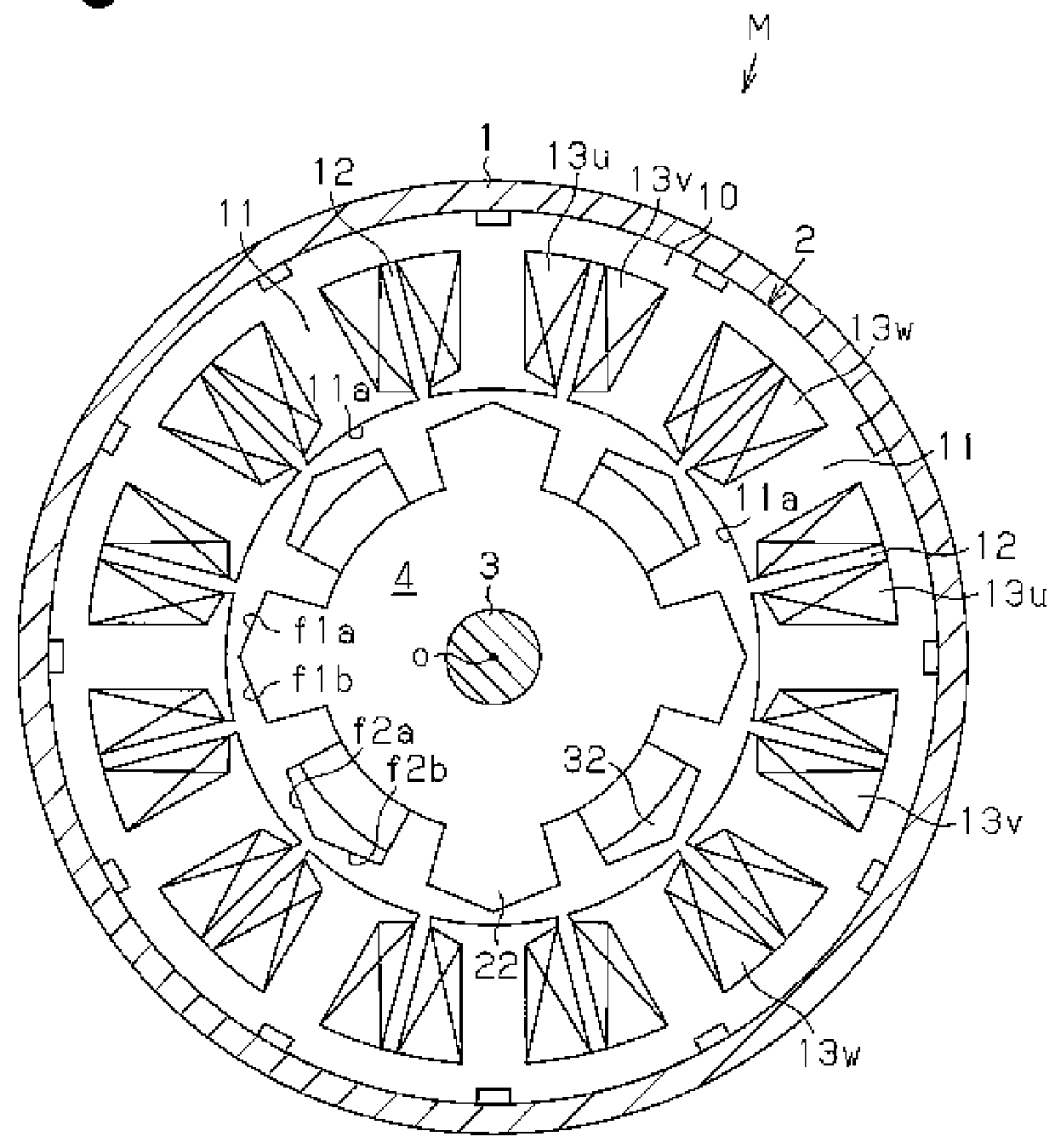
[0082]As shown in FIG. 1, a brushless motor M has a stator 2 fixed to an inner circumferential surface of a motor housing 1. A rotor 4 fixed to a rotation shaft 3 and rotated integrally with the rotation shaft 3 is arranged in the stator 2.
[0083](Stator 2)
[0084]The stator 2 includes a cylindrical stator core 10, and an outer circumferential surface of the stator core 10 is fixed to the motor housing 1. Teeth 11 are formed in the stator core 10 along an axial direction and arranged in a circumferential direction at equal intervals. The teeth 11 are extended toward a radially inner side. Each tooth 11 is T-shaped and includes an inner circumferential surface 11a in the radial direction that is an arcuate surface obtained by extending an arc concentric to a circle of which center is an axis O of the rotation shaft 3 in the axial direction.
[0085]A stator ...
second embodiment
[0127]Next, a second embodiment of the present invention will be described with reference to FIG. 8 to FIG. 14.
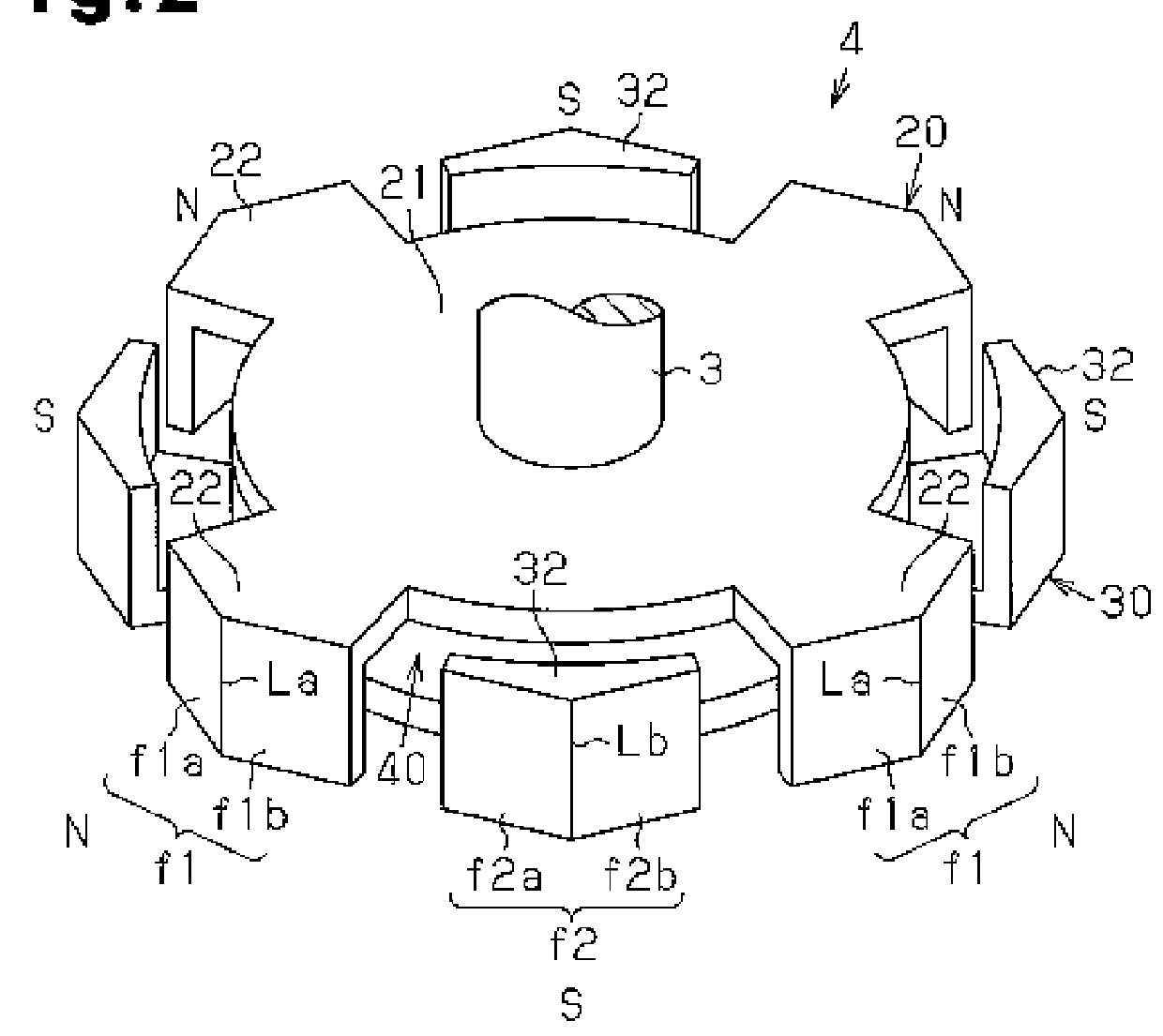
[0128]The present embodiment has characteristics in the radially outer surfaces f1, f2 of the first and second claw magnetic pole portions 22, 32 shown in the first embodiment. Accordingly, the characteristic portions will be described in detail, and portions corresponding with the first embodiment will not be described in detail for the sake of convenience.
[0129]As shown in FIG. 8, a brushless motor M of the present embodiment has a stator 2 fixed to an inner circumferential surface of a motor housing 1, and a rotor 4 that is fixed to and rotates integrally with a rotation shaft 3 is arranged at an inner side of the stator 2.
[0130]The stator 2 includes a stator core 10, and twelve teeth 11 extend from the stator core 10. Each of the teeth 11 is T-shaped, and an inner circumferential surface 11a thereof in a radial direction is an arcuate surface obtained by extending in th...
third embodiment
[0181]Next, a third embodiment of the present invention will be described with reference to FIG. 16 and FIG. 17.
[0182]In the present embodiment, there is a difference only in configurations of first auxiliary grooves 25, 35 and second auxiliary grooves 26, 36 formed on radially outer surfaces f1, f2 of the first and second claw magnetic pole portions 22, 32 shown in the second embodiment. Accordingly, the difference will be described.
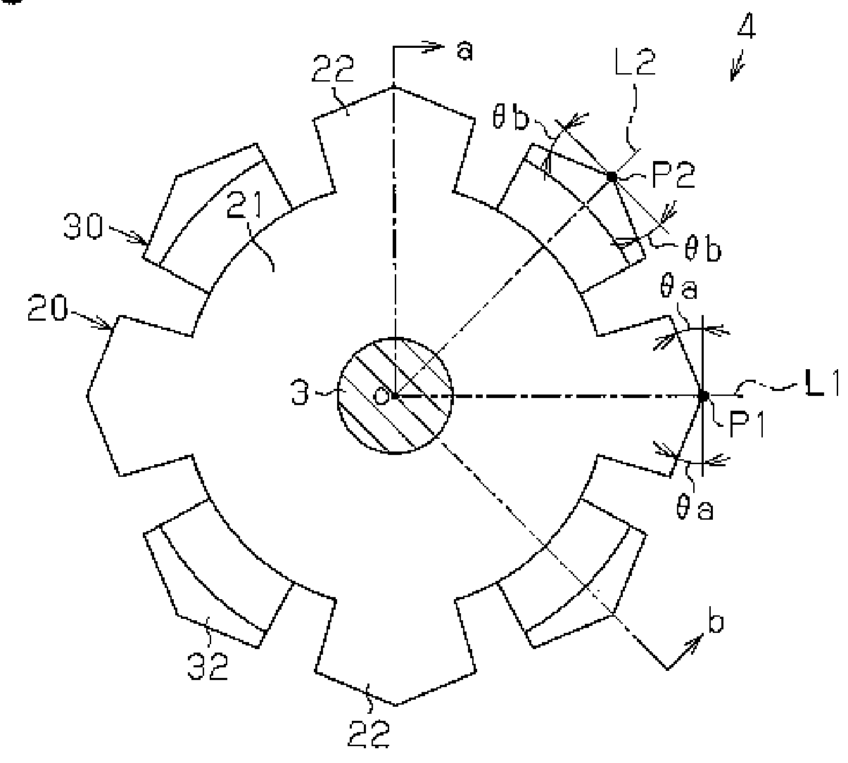
[0183]As shown in FIG. 16, on a radially outer surface f1 of each of the first claw magnetic pole portions 22 of the first rotor core 20, a first left-side auxiliary groove 25L and a first right-side auxiliary groove 25R are formed on both sides in a circumferential direction with a first line L1a as an axis of axial symmetry, and a second left-side auxiliary groove 26L and a second right-side auxiliary groove 26R are formed on both sides in the circumferential direction with a second line L1b as an axis of axial symmetry.
[0184]Accordingly, four auxilia...
PUM
 Abstract
Description
Claims
Application Information
 - R&D
- Intellectual Property
- Life Sciences
- Materials
- Tech Scout
- Unparalleled Data Quality
- Higher Quality Content
- 60% Fewer Hallucinations
Browse by: Latest US Patents, China's latest patents, Technical Efficacy Thesaurus, Application Domain, Technology Topic, Popular Technical Reports.
© 2025 PatSnap. All rights reserved.Legal|Privacy policy|Modern Slavery Act Transparency Statement|Sitemap|About US| Contact US: help@patsnap.com